SAAB 9000. Manual — part 54
12•8 Body electrical systems
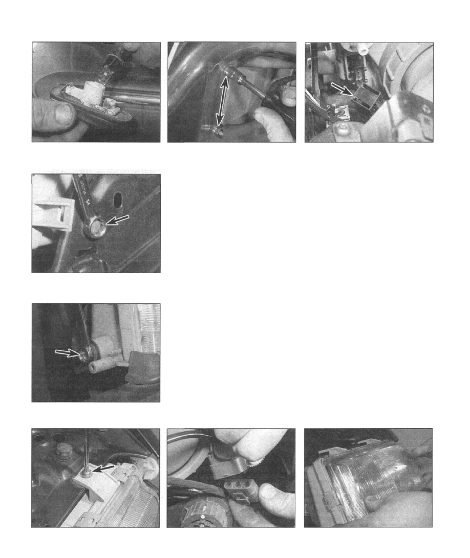
6.19 Withdraw the bulbholder from the light
unit
6.35a Remove the retaining screws from
the headlight unit - one on the left...
6.35b . . . one on the right-hand side .
6.23 Removing two of the reflector panel
retaining nuts (arrowed)
19 Withdraw the bulbholder from the light unit
(see illustration).
20 Refitting is a reversal of removal, ensuring
that the rubber seal is evenly seated.
Reversing light/rear foglight/
reflector panel assembly (later
models only)
21 On later models, the rear fog and reversing
lights are an integral part of the rear reflector
bar, mounted between the rear light clusters.
As such, they must be renewed as part of a
complete assembly.
22 With reference to Chapter 11, remove the
trim panel from the tailgate/boot to expose the
reflector panel mounting nuts.
23 Remove the nuts and lift off the reflector
panel (see illustration).
24 Refitting is a reversal of removal.
Headlight unit
RemovaI
25 Open the bonnet, then with reference to
Chapter 11, remove the front grille.
Earlier models
26 Where applicable, disconnect the washer
jet hose at the connection to the wiper arm.
27 Unplug the wiper motor cable at the three-
way connector.
28 With reference to Section 14, remove the
nut and disconnect the wiper arm from the
drive spindle.
29 Remove the retaining screw, and separate
6.34 Unplug the bulb supply cable from the
light unit at the multi-plug connector
(arrowed)
the wiper motor assembly from the headlight
unit.
30 Unscrew the weatherproof cover from the
rear of the headlight unit, then unplug the bulb
supply cable at the connector.
31 Refer to the relevant sub-section, and
remove the adjacent front light cluster.
32 Remove the retaining screws from the
headlight unit; one on the lower edge behind
the bumper moulding, and two. along the
upper edge.
33 Lift the headlight unit away from the
vehicle.
Later models
34 Unplug the bulb supply cable from the
light unit at the multi-plug connector (see
illustration). Note: Pull the red locking bar out
of the male section of the connector body to
unlock it from the female side.
35 Remove the retaining screws from the
headlight unit - one each on the left and right-
hand sides, and two along the upper edge
(see illustrations).
36 Where applicable, unplug the headlight
levelling motor cable at the connector (see
illustration).
37 Lift the headlight unit out of the vehicle
(see illustration).
Dismantling
38 Refer to Section 7 for details of bulb
removal.
39 To remove the lens, carefully prise off the
metal spring clips; use a screwdriver as a
6.35c... and two along the upper edge
(one shown)
6.36 Unplug the headlight levelling motor
cable at the connector
6.37 Lift the headlight unit out of the
vehicle
Body electrical systems 12•9
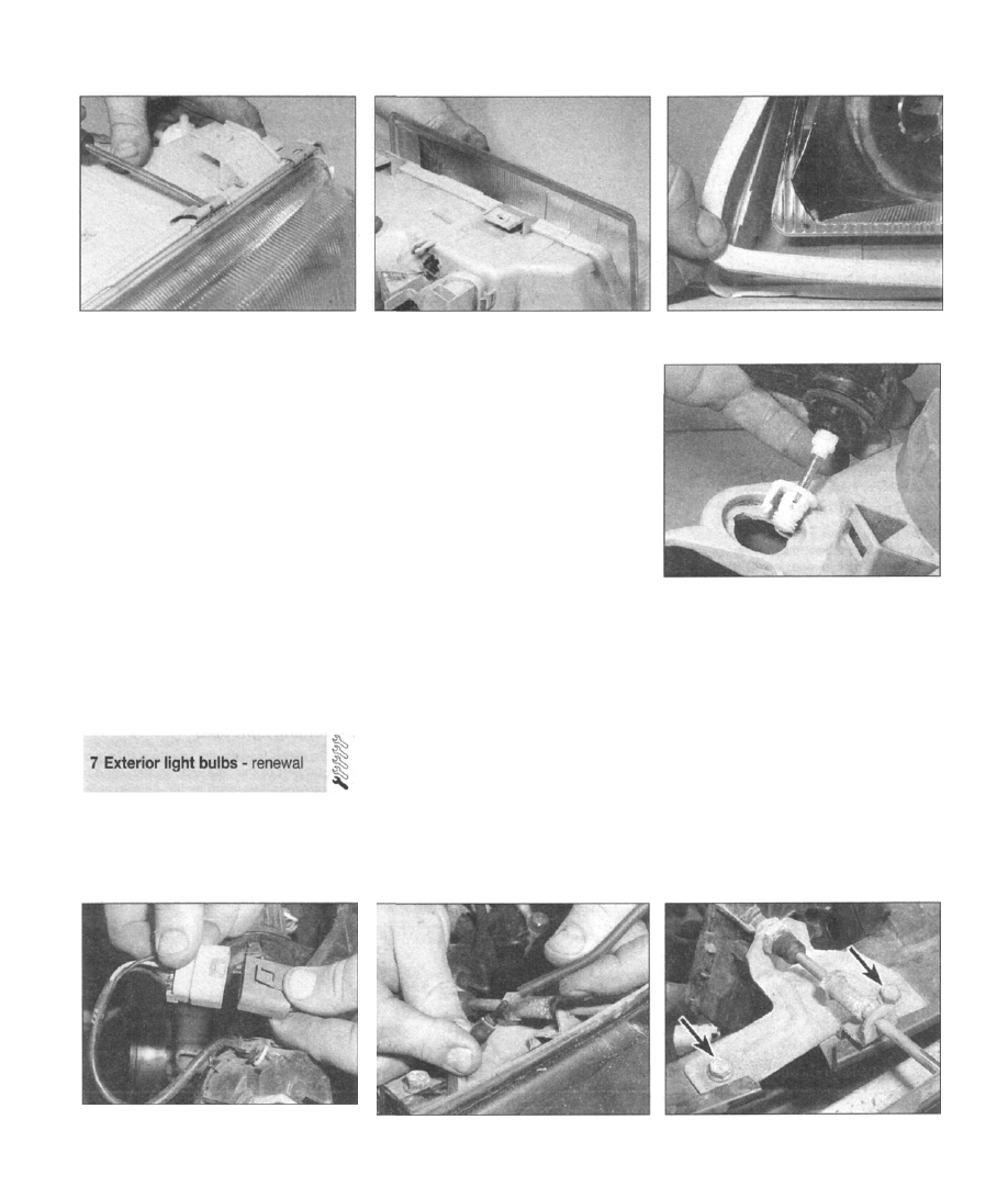
6.39a To remove the lens, carefully prise off
the metal spring clips
lever, but ensure that it bears only on the
plastic body of the light unit, not the glass lens
itself. As the lens is freed, recover the rubber
seal beneath (see illustrations).
40 To remove the headlight levelling motor
(where applicable), reach inside the rear cover
aperture, and unclip the end of the servo
motor shaft from the internal reflector. Twist
the servo motor body until the locking lug is
felt to disengage, and lift the motor out (see
illustration).
41 To remove the headlight wiper motor from
the vehicle on later models, first unplug the
supply cable at the three-way connector.
Disconnect the washer jet hose, then remove
the two retaining screws and lift the entire
assembly away from the vehicle (see
illustrations).
Refitting
42 Refit the light unit by reversing the removal
procedure.
General
1 When renewing bulbs, note the following
points:
a) To eliminate the risk of causing accidental
short-circuits, disconnect the battery
6.39b Removing the lens
negative cable, and position it away from
the terminal.
b) When fitting a new bulb, avoid touching
the glass lens - hold it by the metal flange,
as deposits left by hand contact can
shorten the bulb's service life.
c) Only fit new bulbs of the correct power
rating (refer to the Specifications).
d) Before fitting a new bulb, first check the
condition of the contacts in the bulbholder.
Ensure that there is no corrosion or dirt
that may cause a poor connect/on.
e) The Saab 9000 bulb filament monitoring
system uses a balanced relay to detect
bulb failure. It has been suggested that all
bulbs (except headlamps) should be
replaced in pairs, otherwise the monitoring
systems may pick up the imbalance of
current and indicate a bulbs has failed.
Headlight bulb
General
2 On earlier models, the main and dipped beam
filaments for each headlight are contained in one
bulb, at the centre of a single reflector.
3 Later models are fitted with dual-reflector
headlight units, utilising separate bulbs for
main and dipped beam.
Models with single-reflector headlights
4 Open the bonnet, and from within the
engine bay, pull off the cover from the rear of
the headlight unit.
6.39c Recover the rubber seal beneath
6.40 Removing the headlight levelling
motor
5 Unplug the cable connector, then unhook the
retaining clip and pivot it back to release the bulb.
6 Fit the new bulb, ensuring that the three
locating lugs on the bulbs metal flange engage
with the housing. Press the retaining clip back
into position.
Models with dual-reflector headlights
Dipped beam
7 Open the bonnet, and from within the
engine bay, unscrew the circular cover from
the rear of the headlight unit.
8 The dipped beam bulb is at the centre of the
reflector. Pull off the cable connector, then
unhook the metal retaining clip and lift out the
bulb (see illustration).
9 Refitting is a reversal of removal.
6.41 a To remove the headlight wiper motor
from the vehicle on later models, first
unplug the supply cable at the three-way
connector..
6.41 b . . . disconnect the washer
jet hose ...
6.41 c . . . then remove the two retaining
screws (arrowed)

12•10 Body electrical systems
7.8 Removing the dipped beam bulb
7.11 Removing the main beam bulb
7.22 Removing the direction indicator bulb
Main beam
10 Open the bonnet, and from within the
engine bay, unclip the plastic cover from the
rear of the headlight unit.
11 Unplug the cable connector, then unhook
the metal retaining clip and lift out the bulb
(see illustration).
12 Refitting is a reversal of removal.
Parking light bulb
General
13 On earlier models, the parking light is part
of the front light cluster, below the direction
indicator light.
14 On later models, the parking light is
integrated in the headlight unit, and shares the
same reflector as the dipped beam bulb.
7.24 On later models, prise open the cut-
out panel in the loadspace trim to gain
access to the rear of the light cluster
Models with single-reflector
headlights
15 At the rear of the light unit, unplug the
cable connector, then twist the bulbholder
through quarter of a turn and pull it out of the
light unit. The bulb can then be withdrawn
from the holder.
16 Refitting is a reversal of removal.
Models with dual-reflector headlights
17 Open the bonnet, and from within the
engine bay, unscrew the circular cover from
the rear of the headlight unit.
18 The parking light bulb is offset to one side
of the centre of the reflector. Pull off the cable
connector and lift out the bulbholder; the bulb
can then be withdrawn from the holder.
19 Refitting is a reversal of removal.
Direction indicator bulb (including
side repeaters)
Early models
20 Proceed as described for parking light
bulb renewal.
Later models
21 Remove the direction indicator unit, as
described Section 6.
22 Squeeze together the plastic tangs at the
side of the bulbholder, and rotate it anti-
clockwise through a quarter of a turn. Pull the
bulbholder out of the light unit, then pull the
bulb out of the holder (see illustration).
23 Refitting is a reversal of removal.
Rear light cluster bulbs
24 Open the boot/tailgate to gain access to
the rear of the light clusters. On later models,
prise open the cut-out panel in the loadspace
trim (see illustration).
25 Squeeze together the plastic clips to
release the bulbholder. The bulbs are a
bayonet fit in the holder (see illustration).
26 Refitting is a reversal of removal.
Rear foglight bulb
27 On earlier models, the rear foglight is an
integral part of the rear light cluster; refer to
the previous sub-section for details of its
renewal.
28 On later models, open the boot/tailgate,
then unclip the plastic panel from the rear of
the light unit and withdraw the bulbholder; the
bulb is a bayonet fit in the holder (see
illustrations).
29 Refitting is a reversal of removal.
Reversing light bulb
30 On earlier models, the reversing light is an
integral part of the rear light cluster; refer to
the previous sub-section for details of its
renewal.
31 On later models, proceed as in the
description given for the rear foglight renewal.
32 Refitting is a reversal of removal.
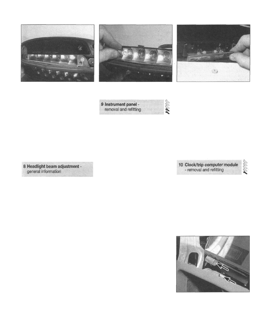
High-level brake light bulbs
33 Remove the two screws, and separate the
7.25 The bulbs are a bayonet fit in the
holder
7.28a Unclip the plastic panel from the rear
of the light unit
7.28b Removing the rear foglight bulb
Body electrical systems 12•11
7.33 Remove the screws, and separate the
lens and cover moulding from the
bulbholder assembly
lens and cover moulding from the bulbholder
assembly (see illustration).
34 The bulbs are push fit in the holder (see
illustration).
35 Refitting is reversal of removal.
Rear number plate bulb
36 Remove the two screws from the lens, and
lower the assembly away from the bodywork
(see illustration).
37 Unclip the bulb from the spring-loaded
terminals.
38 Refitting is a reversal of removal.
Accurate adjustment of the headlight beam
is only possible using optical beam-setting
equipment, and this work should therefore be
carried out by a Saab dealer or suitably-
equipped workshop.
Certain models have a headlight beam
adjustment control, which allows the aim of
the headlights to be adjusted to compensate
for variation in the vehicle's payload. The aim
is altered by means of facia-mounted switch,
which controls electric adjuster motors
located in the rear of the headlight assemblies.
The switch should be positioned as follows,
according to the load being carried in the
vehicle:
Switch
position Vehicle load
0 Up to 3 occupants (no more than
one in the rear seat), no luggage.
1 Up to 3 occupants in rear seats,
up to 30 kg in luggage.
2 Up to 3 occupants in rear seats,
up to 90 kg in luggage.
3 Up to 3 occupants in rear seats,
luggage area full -
OR up to 5 occupants, luggage
area full, towing caravan/trailer.
7.34 The bulbs are a push fit in the holder
General
1 The instrument panel is a single module,
housing the speedometer, tachometer,
gauges and warning lights, and EDU display.
2 The top panel of the facia can be removed,
allowing access to the instrument panel
without the need to remove the entire facia
assembly.
Removal
3 Disconnect the battery negative cable, and
position it away from the terminal.
4 Refer to the relevant paragraphs of Chap-
ter 11, Section 27 and remove the panel from
the top of the facia.
5 With reference to Chapter 3, remove the air
ducting from above the instrument panel.
6 At the rear of the instrument panel,
disconnect all the multi-plug cable
connectors, labelling them to aid refitting later.
7 Where applicable, disconnect the
speedometer drive cable from the rear of the
instrument panel.
8 On turbocharged vehicles, unplug the boost
gauge hose from the rear of the instrument
panel.
9 Remove the two retaining screws from the
top corners of the instrument panel. Note that
the screw heads face the bulkhead, and so
must be extracted from within the facia, using
a short-handled screwdriver. Recover the
rubber mounting bushes.
10 Lift the instrument panel out through the
top of the facia, and recover the rubber
mounting feet
11 Refer to Section 5 for guidance in
renewing the instrument panel illumination and
warning panel bulbs.
12 The instrument panel is modular in design,
and as such, it is possible to renew individual
gauges by simply removing the retaining
screws and lifting the required gauge out.
Refitting
13 Refit the instrument panel by reversing the
7.36 Removing the rear number plate light
bulb
removal procedure, noting the following
points:
a) As the instrument panel is lowered into
position, ensure that the rubber mounting
feet locate in the indentations on the metal
mounting brackets (see illustration)
b) Ensure that the multi-plug cable
connectors are refitted according to the
notes made during removal, and that they
are firmly plugged in.
c) Make reference to the relevant paragraphs
of Chapter 11, Section 27 when fitting the
top panel of the facia; ensure that all
retaining screws are correctly refitted.
General
1 The clock/trip computer module varies in
function and appearance according to the
specification of the vehicle, but the module
housing (and hence the removal procedure)
remains the same.
2 The top panel of the facia can be removed,
allowing access to the module without the
need to remove the entire facia assembly.
3 The EDU display panel is an integral part of
the instrument panel, refer to Section 9 for
details of its removal.
9.13 As the instrument panel is lowered
into position, ensure that the rubber
mounting feet locate in the indentations on
the metal mounting brackets (arrowed)
Нет комментариевНе стесняйтесь поделиться с нами вашим ценным мнением.
Текст