Seat Mii (2019 year). Manual in english — page 2
The essentials
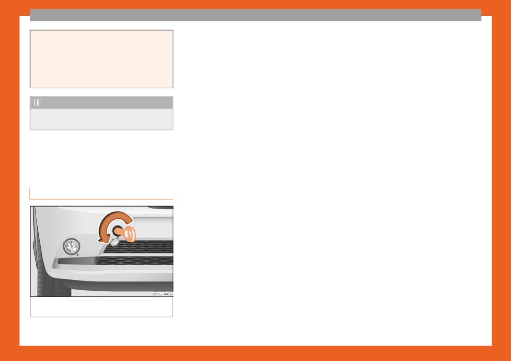
Removing ice from the windscreen
The ››› Fig. 38 button is used to remove ice from the windscreen as quickly as possible and to demist it (defrost/demist function).
When the temperature is above +3°C (+38°F), the air is dehumidified and fan speed increases.
Air recirculation
The ››› Fig. 38 button switches that air recirculation on and off ››› page 129.
Heated rear window
The button, located in the upper part of the centre console, switches the heated rear window on and off when the engine is running. The
heated rear window switches off automatically after 10 minutes at most.
››› in Introduction on page 129
››› page 129
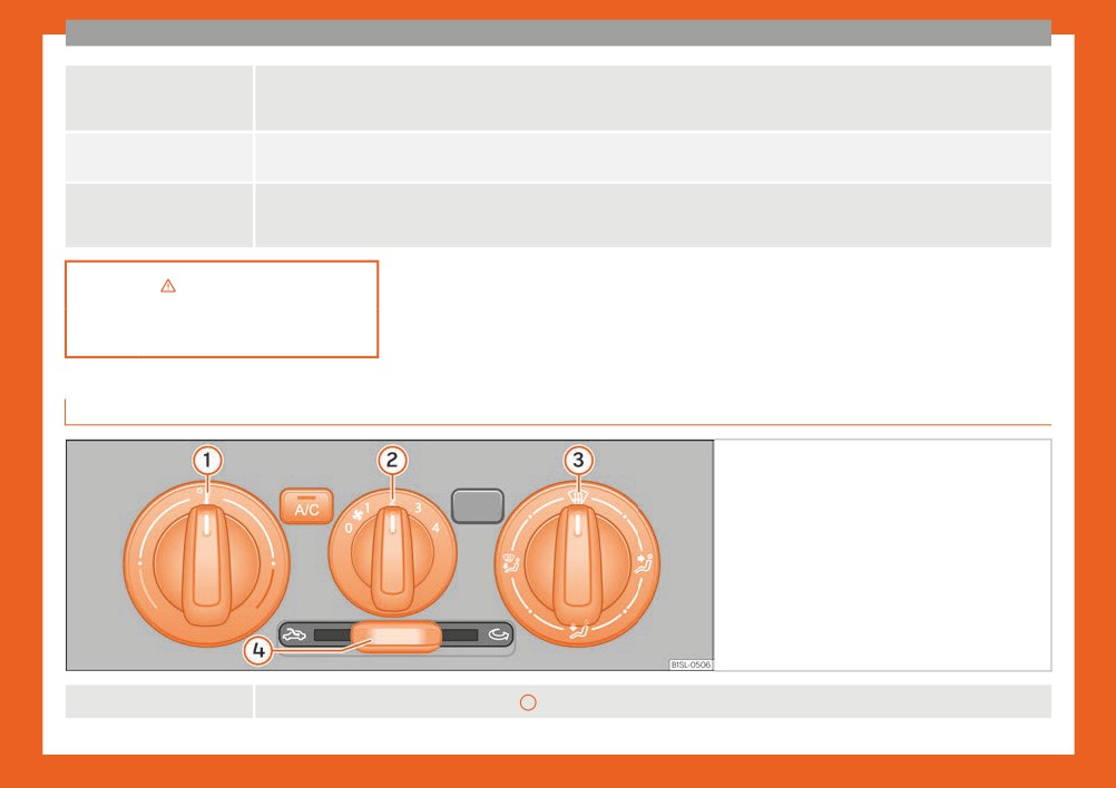
How does the manual air conditioning and the heating and fresh air system work?
Fig. 39 Centre console, top section: controls for
the manual air conditioning and the heating and
fresh air system.
Switching off
It is switched off by turning the central control
2 to the ››› Fig. 39 position.
30

The essentials
Cooling modea)
The button switches cooling mode on and off.
Temperature
The left rotary adjuster
1
››› Fig. 39 is used to adjust the temperature.
Fan
The central rotary adjuster 2 ››› Fig. 39 is used to adjust fan speed.
The right rotary adjuster 3 ››› Fig. 39 is used to adjust air distribution.
: The air is distributed towards the upper part of the body through the dash panel air vents.
: Air distribution to footwells.
Air distribution
: Air distribution towards the windscreen and the footwell.
: Removing ice from the windscreen. Ice is removed from the windscreen as fast as possible and the windscreen is demisted (defrost
function).
Air recirculation
The slider 4 ››› Fig. 39 is used to switch air recirculation on and off ››› page 129.
Heated rear window
The button, located in the upper part of the centre console, switches the heated rear window on and off when the engine is running. The
heated rear window switches off automatically after 10 minutes at most.
a) Valid for vehicles with manual air conditioning.
››› in Introduction on page 129
››› page 129
31
The essentials
Opening the fuel tank cap
Oil
Fluid level control
The tank flap is at the rear of the vehicle on
Filling the fuel tank
the right.
● Pull the rear zone of the fuel tank flap to
Fuel tank capacity
open.
Around 35.0 l
● Unfold the key shaft if necessary
Petrol engines
of which approx. 4.0 l are reserve.
››› page 92.
Natural gas: approx. 11.0 kg; of
● Insert the vehicle key into the lock cylinder
Natural gas
which max. 1.5 kg are reserve
of the fuel tank plug and turn the key in an
engine
Petrol: approx. 10.0 l; of which ap-
anticlockwise direction.
prox. 5.0 l are reserve
● Take out the fuel tank plug by turning it in an
Fig. 41
Engine oil dipstick.
anticlockwise direction and rest it on the up-
Windscreen washer tank capacity
per part of the fuel tank flap ››› Fig. 40.
The washer bottle capacity is approximately 3 litres.
Closing the fuel tank cap
● Screw on the fuel tank filler plug in a clock-
wise direction until it is fully inserted with a
Fuel
click.
● Insert the vehicle key into the lock cylinder
of the fuel tank plug, turn the key in a clock-
wise direction and remove the key.
● Press the tank flap until you hear it click into
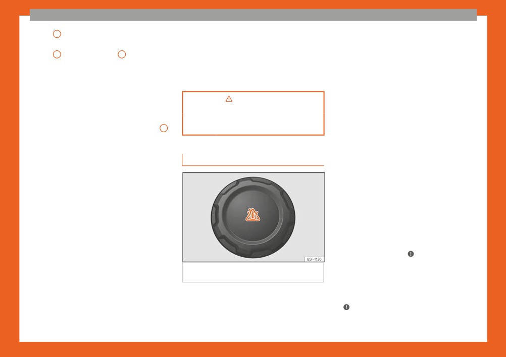
Fig. 42 In the engine compartment: Engine oil
place. The tank flap must be flush with the
filler cap.
body contour.
The level is measured using the dipstick loca-
ted in the engine compartment.
››› in Introduction on page 189
The oil indicator must be between zones A
Fig. 40 Open fuel tank flap with tank cap in
and C . It can never go above zone A .
››› page 191
the holder
● Zone A : do not add oil.
32
The essentials
● Zone B : you can add oil but keep the level
Coolant specifications
in that zone.
Recommended by SEAT
The engine cooling system is supplied from
● Zone C : add oil until zone B .
the factory with a specially treated mixture of
SEAT recommends using original SEAT oil to
water and at least 40 % of the additive G13
Topping up engine oil
guarantee high SEAT engine performance.
(TL-VW 774 J), purple. This mixture gives the
necessary frost protection down to -25°C
● Unscrew cap from oil filler opening.
(-13°F) and protects the light alloy parts of
● Add oil slowly.
the engine cooling system against corrosion.
● At the same time, check the level to ensure
p›age
197
It also prevents scaling and considerably rai-
you do not add too much.
ses the boiling point of the coolant.
● When the oil level reaches at least zone B ,
››› page 195
To protect the cooling system, the percent-
unscrew the engine oil filler cap carefully.
age of additive must always be at least 40 %,
even in warm climates where anti-freeze pro-
If the engine oil level is too low
tection is not required.
Coolant
You can get information about the correct en-
If for weather reasons further protection is
gine oil for your vehicle in your specialised
necessary, the proportion of additive may be
shop. If you have to change your engine oil,
increased, but only up to 60 %; otherwise an-
use this oil.
tifreeze protection will diminish and this will
If the recommended engine oil is not availa-
worsen cooling.
ble, in the event of an emergency you can
When the coolant is topped up, use a mixture
change the oil once with a maximum of 0.5 L
of distilled water and at least 40 % of the
of the next oil until the next oil change:
G13 or G12 plus-plus (TL-VW 774 G) additive
(both are purple) to obtain an optimum anti-
- Petrol engines: standard VW 504 00,
corrosion protection ››› in Checking the
VW 502 00, VW 508 00, ACEA C3 or
coolant level and topping up on page 200.
API SN.
Fig. 43 Engine compartment: coolant expan-
The mixture of G13 with G12 plus (TL-VW 774
sion tank cap.
Have the oil changed by a specialised work-
F), G12 (red) or G11 (green-blue) engine cool-
shop.
ants will significantly reduce anti-corrosion
The coolant tank is located in the engine
protection and should therefore be avoided
Using engine oil that is compliant with the VW
compartment.
››› in Checking the coolant level and
504 00 standard instead of VW 508 00
When the engine is cold, replace the coolant
topping up on page 200.
»
could increase consumption and the vehicle’s
when the level is below .
CO2 emissions.
33
The essentials
Windscreen washer
Battery
a›nd
opping up on page 199
The battery is located in the engine compart-
ment. It does not require maintenance. It is
››› page 198
checked as part of the Inspection Service.
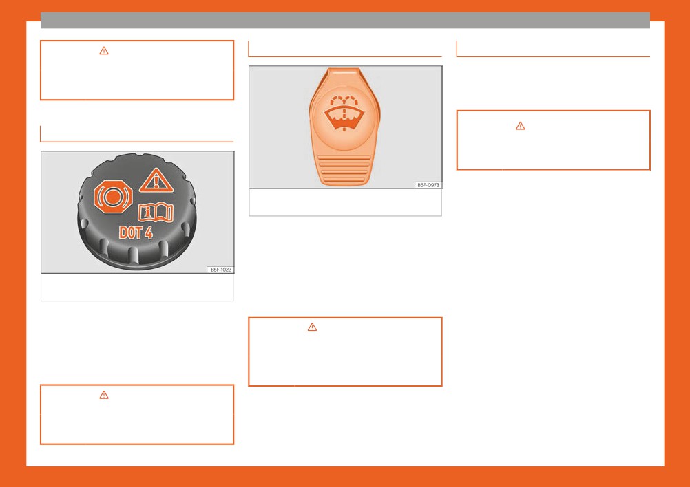
Brake fluid
››› in Introduction on page 203
››› page 202
Fig. 45 In the engine compartment: cap of the
windscreen washer tank.
The windscreen washer reservoir is located in
the engine compartment.
To top up, mix water with a product recom-
mended by SEAT.
Fig. 44 Engine compartment: brake fluid res-
ervoir cap.
In cold temperatures, add anti-freeze for the
windshield cleaner.
The brake fluid reservoir is located in the en-
gine compartment.
››
in Checking and topping up the
windscreen washer reservoir with
The level should be between the and
›
water on page 202
marks. If it is below , please visit a Technical
Service.
››› page 201
e›lonpna
ge 201
››› page 200
34

The essentials
Underneath the instrument panel
Replacing a blown fuse
Emergencies
The fuse box is located underneath the dash
panel on the driver side ››› Fig. 46.
Fuses
In the engine compartment
Fuse location
Press the locking tabs to release the fuse box
cover ››› Fig. 47.
Identifying fuses situated below the dash
panel by colours
Colour
Amp rating
Fig. 48 Image of a blown fuse.
Purple
3
Preparation
Light brown
5
● Switch off the ignition, lights and all electri-
Brown
7.5
cal equipment.
Fig. 46 On the dashboard on the driver side:
Red
10
● Open the corresponding fuse box
lid of the fuse box.
Blue
15
››› page 79.
Yellow
20
Identifying a blown fuse
White or transparent
25
A fuse is blown if its metal strip is ruptured
››› Fig. 48.
Green
30
Point a lamp at the fuse to see if the fuse has
Orange
40
blown.
To replace a fuse
››› in Introduction on page 78
● Remove the fuse.
Fig. 47 In the engine compartment: lid of the
● Replace the blown fuse by one with an
››› page 78
fuse box.
identical amperage rating (same colour and
markings) and identical size.
»
35
The essentials
● Replace the cover again or close the fuse
Action in the event of a punc-
with a stone or similar to prevent the vehi-
box lid.
cle from moving.
ture
What to do first
Bulbs
Repairing a tyre with the anti-punc-
● Park the vehicle on a horizontal surface and
ture kit
Bulbs (12 V)
in a safe place as far away from traffic as
possible.
Light source used for each function
● Apply the handbrake.
Halogen headlights.
Type
● Switch on the hazard warning lights.
Daytime running light/side
● Manual transmission: select the 1st gear.
W21/5W
light
● Automatic transmission: Move the selector
Dipped beam headlights
H4 LL
lever to position D or R.
● If you are towing a trailer, unhitch it from
Main beam headlights
H4 LL
your vehicle.
Turn signal
PY21W NA
● Have the vehicle tool kit ››› page 71
and the spare wheel* ready
Rear bulb light
Type
››› page 213.
Fig. 49 Standard display: contents of the anti-
Brake/side lights
P21/5W LL
● Observe the applicable legislation for each
puncture kit.
country (reflective vest, warning triangles,
Side lights
P21/5W LL
etc.).
The anti-puncture kit is located under the
Turn signal
PY21W NA LL
● All occupants should leave the vehicle and
floor panel in the luggage compartment.
wait in a safe place (for instance behind the
Retro fog light
P21W
roadside crash barrier).
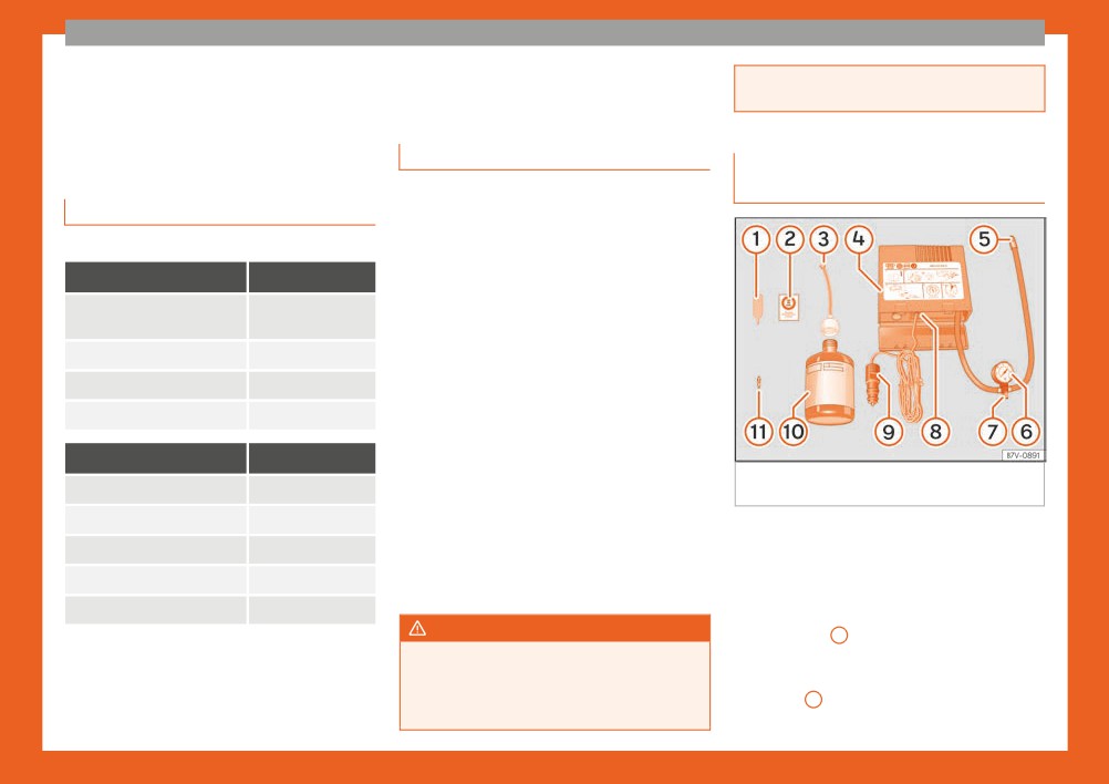
Sealing the tyre
Reverse lights
R10W
● Unscrew the tyre valve cap and insert. Use
WARNING
the ››› Fig. 49
1 tool to remove the insert.
● Always observe the above steps and pro-
Place it on a clean surface.
tect yourself and other road users.
● Shake the tyre sealant bottle vigorously
● If you change the wheel on a slope, block
››› Fig. 49 10 .
the wheel on the opposite side of the car
36
The essentials
● Screw the inflator tube ››› Fig. 49 3 into
● Move the vehicle 10m so that the sealant is
Changing a wheel
the sealant bottle. The bottle's seal will break
distributed throughout the tyre.
automatically.
● Screw the compressor tyre inflator into the
Vehicle tool kit
● Remove the lid from the filling tube
valve.
››› Fig. 49 3 and screw the open end of the
● Repeat the inflation process.
tube into the tyre valve.
● If the indicated pressure still cannot be
● With the tyre sealant bottle upside down, fill
reached, the tyre is too badly damaged. Stop
the tyre with the contents of the sealant bot-
and request assistance from an authorised
tle.
technician.
● Remove the bottle from the valve.
● Disconnect the air compressor. Unscrew
● Place the insert back into the tyre valve us-
the tyre inflator tube from the tyre valve.
ing the tool ››› Fig. 49
1 .
● When the tyre pressure is between 2.5 and
2.0 bars, continue driving without exceeding
Inflating the tyre
80 km/h (50 mph).
● Screw the compressor tyre inflator tube
● Attach the sticker ››› Fig. 49 2 to the in-
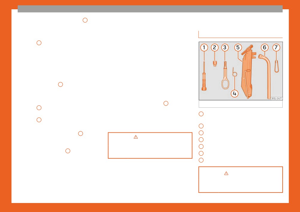
Fig. 50 Components of the vehicle tool kit
››› Fig. 49 5 into the tyre valve.
strument cluster, within the driver's visual
● Check that the air bleed screw is closed
field.
1
Screwdriver with hexagon socket in the
››› Fig. 49
7 .
● Check the pressure again after 10 minutes
handle
● Start the engine and leave it running.
››› page 74.
2
Adapter for anti-theft bolt.
● Insert the connector ››› Fig. 49 9 into the
3
Towline anchorage, removable.
vehicle's 12-volt socket ››› page 120.
4
Wire hook for removing the hub caps.
o›npa
ge 73
● Turn the air compressor on with the
5
Jack.
ON/OFF switch ››› Fig. 49 8 .
››› page 73
6
Wheel spanner.
● Keep the air compressor running until it rea-
7
Wheel bolt cap clips.
ches 2.0 to 2.5 bar (29-36 psi/200-250 kPa).
A maximum of 8 minutes.
● Disconnect the air compressor.
››› in What to do first on page 36
● If it does not reach the pressure indicated,
unscrew the tyre inflator tube from the valve.
››› page 70
37
The essentials
Hubcaps
Full hubcaps
Wheel bolt caps
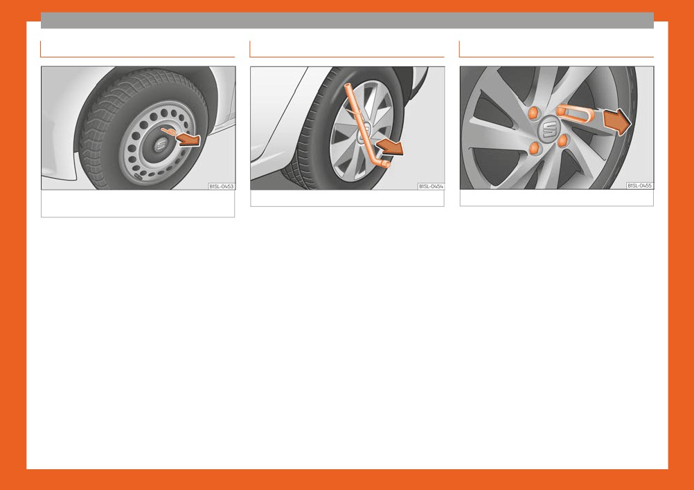
Fig. 51 Remove the hubcap of the steel wheel
Fig. 52 Removing the full hubcap
Fig. 53 Removing the wheel bolt caps
trim
Removing the full hubcap
Removal
In order to access the wheel bolts, first re-
● Take the wheel brace and the wire hook
● Fit the plastic clip (vehicle tools
move the hubcap.
from the vehicle tool kit ››› page 70.
››› page 70) over the cap until it clicks
into place ››› Fig. 53.
Removing and fitting the hubcap
● Hook the wire through one of the grooves
on the hubcap.
● Remove the cap with the plastic clip.
● To remove, take the vehicle tool kit wire
● Insert the wheel brace onto the wire hook
hook and attach it to the edge of the wheel
The caps protect the wheel bolts and should
››› Fig. 52 and pull the hub cap in the direc-
trim ››› Fig. 51.
be remounted after changing the tyre.
tion shown by the arrow.
● Remove the trim by pulling it in the direction
The anti-theft wheel bolt has a special cap
of the arrow.
which is only compatible with anti-theft bolts
Fitting hubcaps
● To replace the hubcap, press the hubcap
and cannot be used for conventional bolts.
● It is necessary to press the hubcap against
against the trim until it clicks into place.
the wheel so that the space for the valve fits
The caps protect the wheel bolts and should
over the tyre valve.
be remounted after changing the tyre.
● Make sure that the hubcap is correctly fit-
ted all the way around the wheel. If you are
using an anti-theft wheel lock, screw it in the
opposite position to the valve.
38
The essentials
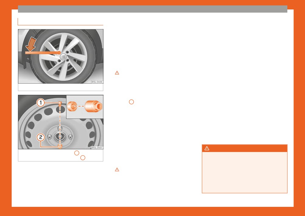
Loosening the wheel bolts
of the wheel brace carefully with your foot.
with the right length and correctly shaped
Hold on to the vehicle for support and take
bolt heads must be used. This ensures that
care not to slip.
wheels are fitted securely and that the brake
system functions correctly.
Loosening wheel bolts
In some circumstances, wheel bolts from the
● Fit the wheel brace as far as it will go over
same model vehicle should not be used.
the wheel bolt ››› Fig. 54.
● Hold the wheel brace at the end and rotate
Wheel bolt tightening torque
the bolt approximately one turn anticlockwise
The prescribed tightening torque for wheel
›››
bolts for steel and alloy wheels is 110 Nm.
Have the tightening torque of the wheel bolts
Loosening anti-theft wheel bolts
checked as soon as possible with a reliable
Fig. 54
Tyre change: slacken the wheel bolts.
For wheels with full hubcap, the anti-theft
torque wrench.
wheel lock must be threaded into position
If wheel bolts are rusty and it is difficult to
››› Fig. 55 2 before mounting the hubcap.
tighten them, the threads should be replaced
Otherwise it will not be possible to mount the
and cleaned before checking the tighten-
entire hubcap.
ing torque.
● Take the adapter for anti-theft wheel bolts
Never grease or lubricate wheel bolts or the
out of the vehicle tool kit.
wheel hub threads. Although they have been
tightened to the prescribed torque, they
● Insert the adapter onto the wheel bolt
could come loose while driving.
››› Fig. 55. Push it on as far as it will go.
● Fit the wheel brace onto the adapter as far
WARNING
Fig. 55
Tyre change: tyre valve
1 and posi-
as possible.
If the wheel bolts are not fitted correctly
tion of anti-theft wheel locking bolt
2 .
● Hold the wheel brace at the end and rotate
they could be released while driving lead-
the bolt approximately one turn anticlockwise
● Only use the tool supplied with the vehicle
ing to loss of vehicle control and serious
›››
damage.
to loosen the wheel bolts.
● Only use wheel bolts which correspond
● Loosen the wheel bolts only about one turn
Important information about wheel bolts
to the wheel rims in question.
before raising the vehicle with the jack.
The wheel rims and bolts have been de-
● Never use different wheel bolts.
»
● If the wheel bolt is very tight, you may be
signed to be fitted to factory options. If differ-
able to loosen it by pushing down on the end
ent rims are fitted, the correct wheel bolts
39
The essentials
● The bolts and threads should be clean,
Raising the vehicle with the jack
free of oil and grease and easy to thread.
● To loosen and tighten the wheel bolts, al-
ways use the wheel brace supplied with the
vehicle.
● Loosen the wheel bolts only about one
turn before raising the vehicle with the jack.
● Never grease or lubricate wheel bolts or
the wheel hub threads. Although they have
been tightened to the prescribed torque,
they could come loose while driving.
● Never loosen the bolted joints of wheel
Fig. 56
Jack position points.
rims with bolted ring trims.
● If the wheel bolts are not tightened to the
correct torque, they may come loose while
driving, and the bolts and rims may come
out. If the tightening torque is too high, the
wheel bolts and threads can be damaged.
Fig. 57 Jack mounted on the left rear part of
the vehicle
The jack may be applied only at the jacking
points shown (marks on chassis) ››› Fig. 56.
Always the relevant jacking point for the
wheel to be changed ›››
Raise the vehicle using only the designated
jacking points.
40
The essentials
WARNING
Removing and fitting a wheel
● Place the spare wheel or temporary spare
wheel into position.
If the vehicle is not correctly raised, it could
● Replace the wheel bolts and tighten slight-
fall off the jack causing serious injury.
Please observe the following rules to mini-
ly using the hexagonal socket on the end of
mise the risk of injury:
the wheel brace.
● You should only use a jack approved by
● To tighten the anti-theft locking wheel bolts
SEAT for your vehicle. Other jacks, even
use the corresponding adaptor.
those approved for other SEAT models,
● Lower the car with the jack.
might slip out of place.
● Tighten all of the wheel bolts clockwise
● The ground should be firm and flat. If the
››› . Tighten the bolts in diagonal pairs (not
ground is sloped or soft then the vehicle
in a circle).
could slip and fall off the jack. If necessary,
support the jack on a wide solid base.
Fig. 58 Changing the tyre: loosen wheel bolts
● Put the caps, trim or full hubcap back on
with the socket at the end of the wheel brace
››› page 38.
● If the ground is slippery, such as tiles,
place a non-slip surface (a floor mat, for in-
Change the wheel after loosening the wheel
stance) beneath the jack to avoid slipping.
WARNING
bolts and raising the vehicle with the jack.
● Only fit the jack at the prescribed jacking
If the wheel bolts are not treated suitably
points. The claw of the jack should grip the
or not tightened to the correct torque then
Removing the wheel
reinforcement nerve on the underbody
this could lead to loss of vehicle control
››› Fig. 57.
● Slacken the wheel bolts ››› page 39.
and to a serious accident.
● You should never place a body limb such
● Raise the vehicle ››› page 40.
● All the wheel bolts and hub threads
as an arm or leg under a raised vehicle that
● Using the hexagonal socket in the wheel
should be clean and free of oil and grease.
is solely supported by the jack.
The wheel bolts should be easily tightened
brace ››› Fig. 58, unscrew the slackened
to the correct torque.
● If you have to work underneath the vehi-
wheel bolts and place them on a clean sur-
cle, you must use suitable stands addition-
face.
● The hexagonal socket in the wheel brace
ally to support the vehicle, there is a risk of
should be used for turning wheel bolts only.
● Take off the wheel.
accident!.
Do not use it to loosen or tighten the wheel
bolts.
● Never raise the vehicle if it is tilting to one
How to use the spare wheel or temporary
side or the engine is running.
spare wheel
● Never start the engine when the vehicle is
Check the direction of rotation of the tyre
raised. The vehicle may come loose from
››› page 214, Tyre code.
the jack due to the engine vibrations.
41
The essentials
Tyres with compulsory direction of
● Have the tightening torque of the wheel
Remove wheel hub covers and trim rings be-
bolts checked as soon as possible with a tor-
fore fitting snow chains ››› . The wheel bolts
rotation
que wrench ›››
page 39.
should be covered with caps for safety rea-
sons. These are available from technical
A directional tread pattern can be identified
● Have the flat tyre replaced as quickly as
by the arrows on the sidewall that point in the
possible.
services.
direction of rotation. Always observe the di-
rection of rotation indicated when fitting the
Temporary spare wheel
wheel to guarantee optimum properties of
For technical reasons, snow chains must not
this type of tyres with regard to grip, noises,
Snow chains
be used on the compact temporary spare
wear and aquaplaning.
wheel ››› page 213.
Use
If it is absolutely necessary to fit the spare
If it is necessary to fit chains with the tempo-
tyre* against the direction of rotation, drive
rary spare wheel in use, install the wheel on
When using snow chains, applicable local
with care as this means the tyre does not of-
the rear axle in the event of a fault in a front
legislation and maximum permitted speed
fer optimum driving properties. This is of par-
wheel. Then, fit the rear wheel that is free, in-
limits must be observed.
ticular importance when the road surface is
stead of the damaged front wheel. In this sit-
wet.
In winter weather, snow chains not only help
uation, observe the rotating direction of the
to improve grip but also improve the braking
wheels. SEAT recommends attaching the
To return to directional tread tires, replace the
capacity.
snow chains before fitting the wheel.
punctured tyre as soon as possible and re-
store the obligatory direction of rotation of all
The fitting of chains is permitted only on
tyres.
front wheels and with the following combi-
WARNING
nations of wheel trims and tyres:
The use of unsuitable or incorrectly fitted
chains could lead to serious accidents and
Tyre size
Wheel rim
damage.
After the wheel change
● Always the appropriate snow chains.
165/70 R14
● Clean the vehicle tools, if necessary and
5 J x 14 offset of 35
● Observe the fitting instructions provided
put them away in the luggage compartment
175/65 R14
by the snow chain manufacturer.
foam holder ››› page 70.
● Never exceed the maximum permitted
SEAT recommends you ask a technical serv-
● Store the spare wheel, the temporary spare
speeds when driving with snow chains.
ice for further information on wheel, tyre and
wheel or the changed wheel securely in the
chain sizes.
luggage compartment.
CAUTION
Wherever possible use fine-link chains meas-
uring less than 15 mm including the lock.
● Remove the snow chains to drive on
roads without snow. Otherwise they will
42
The essentials
impair vehicle handling, damage the tyres
Towline anchorages
● The brake must be depressed much harder
and wear out very quickly.
Attach the bar or rope to the towline ancho-
as the brake servo does not operate. Avoid
hitting the towing vehicle.
● Wheel rims may be damaged or scratch-
rages.
ed if the chains come into direct contact
● Note the instructions and information con-
It is located with the vehicle's tools
with them. SEAT recommends the use of
tained in the Instruction Manual for the vehi-
››› page 70.
covered snow chains.
cle to be towed.
Screw the front towline anchorage into the
screw connection ››› Fig. 59 and tighten it
Notes for the driver of the towing vehicle
Note
with the wheel brace.
Snow chains are available in different sizes
● Accelerate gently and carefully. Avoid sud-
according to the vehicle type.
den manoeuvres.
Tow rope or tow bar
● Brake well in advance than usual and brake
When towing, the tow bar is the safest and
gently.
vehicle friendly way. You should only use a
● Note the instructions and information con-
Emergency towing of the ve-
tow rope if you do not have a tow bar.
tained in the Instruction Manual for the vehi-
hicle
A tow rope should be slightly elastic to avoid
cle to be towed.
damage to both vehicles. It is advisable to
use a tow rope made of synthetic fibre or sim-
Driving style
Towing
ilarly elastic material.
Towing requires some experience, especially
● Only secure the tow rope or tow bar to the
when using a tow rope. Both drivers should
towline anchorage or specially designed fit-
realise how difficult it is to tow a vehicle. Inex-
ting.
perienced drivers should not attempt to tow.
Do not pull too hard with the towing vehicle
Notes for the driver of the towed vehicle
and take care to avoid jerking the tow rope.
● Keep the ignition running to prevent the
When towing on an unpaved road, there is al-
steering wheel from locking and also to allow
ways a risk of overloading and damaging the
the use of the turn signals, horn, windscreen
anchorage points.
wipers and washers.
Switch on the ignition so that the turn signals,
● As the power assisted steering does not
windscreen wipers and windscreen washer
Fig. 59 Right side of the front bumper: towline
anchorage screwed in.
work if the engine is not running, you will need
can work. Ensure that the steering wheel is
more strength to steer than normally.
unlocked and moves freely.
»
43
The essentials
Place the gear lever in neutral on vehicles
However, if your vehicle must absolutely
WARNING
with a manual gearbox. With an automatic
be tow-started (manual gearbox):
Incorrect use of jump leads and incorrectly
gearbox, place the lever in N.
● Put it into second or third gear.
jump starting could cause the battery to
To brake, press the brake pedal firmly. The
● Keep the clutch pressed down.
explode resulting in serious injury. Please
brake servo does not work when the engine is
observe the following rules to minimise the
● Switch on the ignition and the hazard warn-
switched off.
risk of a battery explosion:
ing lights.
● The battery providing current must have
The power steering only works when the igni-
● Release the clutch when both vehicles are
the same voltage (12V) and approximately
tion is switched on, provided that the battery
moving.
the same capacity (see markings on bat-
is sufficiently charged. Otherwise, it will need
● As soon as the engine starts, press the
tery) as the flat battery.
more force.
clutch and move the gear lever into neutral.
● Never charge a frozen or recently thawed
Ensure that the tow rope remains taut at all
This helps to prevent a collision with the tow-
battery. A flat battery can also freeze at
times.
ing vehicle.
temperatures close to 0°C (+32°F).
● If a battery is frozen and/or has been fro-
zen then it must be replaced.
o›npa
ge 76
● A highly explosive mixture of gases is re-
How to jump start
leased when the battery is being charged.
››› page 75
Always keep lit cigarettes, flames, sparks
Jump leads
and fire far from the battery. Never use a
mobile telephone when connecting and re-
If the engine fails to start because of a dis-
moving the jump leads.
Tow-starting
charged battery, the battery of another vehi-
● Charge the battery only in well ventila-
cle can be used to start the engine. Before
In general, the vehicle should not be star-
ted areas given that when the battery is
starting, check the magic eye on the battery
charged by outside assistance, it creates a
ted by towing. Jump-starting is much more
››› page 202.
mix of highly explosive gases.
preferable ››› page 44.
For starting assistance, jump lead cables
● Jump leads should never enter into con-
For technical reasons, the following vehicles
conforming to the standard DIN 72553 are re-
tact with moving parts in the engine com-
can not be tow started:
quired (see the cable manufacturer instruc-
partment.
tions). The cable section in vehicles with pet-
● Vehicles with an automatic gearbox.
● Never switch the positive and negative
rol engine must be at least 25 mm2.
poles or connect the jump leads incorrect-
● If the vehicle battery is flat, it is possible that
ly.
the engine control unit does not operate cor-
● Note the instruction manual provided by
rectly.
the manufacturer of the jump leads.
44
The essentials
CAUTION
5.
Connect the other end of the black jump
lead X to a solid metal component bol-
To avoid considerable damage to the vehi-
ted to the engine block or to the engine
cle electrical system, note the following
block itself of the vehicle with the flat
carefully:
battery. Do not connect it to a point near
● If the jump leads are incorrectly connec-
the battery A .
ted, this could result in a short circuit.
6.
Position the leads in such a way that
● The vehicles must not touch each other,
they cannot come into contact with any
otherwise electricity could flow as soon as
moving parts in the engine compart-
the positive terminals are connected.
ment.
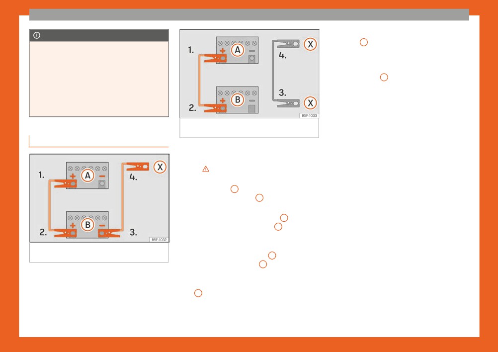
Fig. 61 Diagram of connections for vehicles
with Start Stop system
Starting
How to jump start: description
Start the engine of the vehicle with the
7.
Jump lead terminal connections
boosting battery and let it run at idling
1.
Switch off the ignition of both vehicles
speed.
›››
8.
Start the engine of the vehicle with the
2.
Connect one end of the red jump lead to
flat battery and wait for 2 or 3 minutes
the positive
+ terminal of the vehicle
until the engine is running.
with the flat battery A ››› Fig. 60.
3.
Connect the other end of the red jump
Removing the jump leads
lead to the positive terminal + in the ve-
9.
Before you remove the jump leads,
hicle providing assistance B .
switch off the dipped beam headlights if
4a.
In vehicles without a Start-Stop system:
they are switched on.
Fig. 60 Diagram of connections for vehicles
connect one end of the black jump lead
10.
Turn on the heater blower and heated
without Start Stop system
to the negative terminal - of the vehicle
rear window in the vehicle with the flat
providing the current B ››› Fig. 60.
battery. This helps minimise voltage
4b.
In vehicles with a Start-stop system:
peaks which are generated when the
connect one end of the black jump lead
leads are disconnected.
X to a suitable ground terminal, to a sol-
11.
When the engine is running, disconnect
id piece of metal in the engine block, or
the leads in reverse order to the details
to the engine block itself ››› Fig. 61.
given above.
»
45
The essentials
Make sure the battery clamps have sufficient
● Never attach the negative cable to fuel
Changing the wiper blades
metal-to-metal contact with the battery ter-
system components or the brake lines in
minals.
the other vehicle.
Windscreen wipers service posi-
If the engine fails to start after about 10 sec-
● The non-insulated parts of the battery
tion
onds, switch off the starter and try again after
clamps must not be allowed to touch. The
about 1 minute.
jump lead attached to the positive battery
terminal must not touch metal parts of the
WARNING
vehicle, this can cause a short circuit.
● Position the leads in such a way that they
● Please note the safety warnings referring
cannot come into contact with any moving
to working in the engine compartment
parts in the engine compartment.
››› page 193.
● Do not lean on the batteries. This could
● The battery providing assistance must
result in chemical burns.
have the same voltage as the flat battery
(12V) and approximately the same capaci-
ty (see imprint on battery). Failure to com-
Note
ply could result in an explosion.
The vehicles must not touch each other,
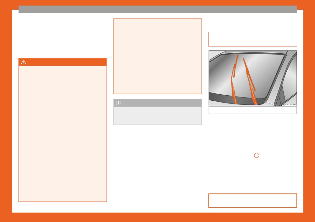
Fig. 62 Wipers in service position.
● Never use jump leads when one of the
otherwise electricity could flow as soon as
batteries is frozen. Danger of explosion!
the positive terminals are connected.
The wiper arms can be raised when the wip-
Even after the battery has thawed, battery
ers are in service position ››› Fig. 62.
acid could leak and cause chemical burns.
If a battery freezes, it should be replaced.
● Close the bonnet ››› page 193.
● Keep sparks, flames and lighted ciga-
● Switch the ignition on and off.
rettes away from batteries, danger of ex-
● Press the windscreen wiper lever down-
plosion. Failure to comply could result in an
wards briefly ››› Fig. 33 4 .
explosion.
● Observe the instructions provided by the
Before driving, always lower the wiper arms.
manufacturer of the jump leads.
When the ignition is switched on, the wind-
● Do not connect the negative cable from
screen wiper arms return to their initial posi-
the other vehicle directly to the negative
tion upon activating the windscreen wiper
terminal of the flat battery. The gas emit-
lever.
ted from the battery could be ignited by
sparks. Danger of explosion.
››› page 75
46
The essentials
Changing the front wiper blades
Cleaning windscreen wiper blades
posite direction to the arrow B and hook into
place. This feature is operational when the
● Lifting and unfolding the wiper arms.
knob is in position (arrow A ).
● Use a soft cloth to remove dust and dirt
● Return the windscreen wiper arm to the
from the windscreen wiper blades.
windscreen. Do not let it simply drop down!
● If the blades are very dirty, a sponge or
damp cloth may be used ››› in Changing
›››
in Changing the windscreen
the windscreen and rear window wiper
and rear window wiper blades on
blades on page 75.
page 75
Changing the windscreen wiper blades
››› page 75
● Lifting and unfolding the wiper arms.
Fig. 63
Changing the front wiper blades
● Hold down the release button ››› Fig. 63 1
while gently pulling the blade in the direction
of the arrow.
● Fit a new wiper blade of the same length
and design on to the wiper arm and hook it
into place.
● Rest the wiper arms back onto the wind-
screen.
Changing the rear wiper blade
● Lift the windscreen wiper arm and fold it at
Fig. 64
Changing the rear wiper blade
an angle of approximately 60° ››› Fig. 64.
● Press and hold the release button
1 .
Lifting and unfolding the wiper arms
● Fold the wiper blade towards the wind-
The wiper arm may only be lifted at the point
screen wiper arm ››› Fig. 64 (arrow A ) while
where it is fastened to the blade.
pulling in the direction of arrow B . You might
The wiper should be in service position before
have to apply a lot of force.
unfolding it ››› page 108.
● Insert a new blade of the same length and
type in the windscreen wiper arm in the op-
47
Safety
Before driving
- Fasten your seat belt securely. Instruct your
Safety
passengers also to fasten their seat belts
For your own safety and the safety of your
properly ››› page 53.
passengers, always note the following points
Safe driving
before every trip:
- Make sure that the vehicle's lights and turn
What affects driving safety?
Driving advice
signals are working properly.
As a driver, you are responsible for yourself
Safety first!
- Check tyre pressure.
and your passengers. When your concentra-
- Ensure that all windows provide a clear and
tion or driving safety is affected by any cir-
WARNING
good view of the surroundings.
cumstance, you endanger yourself as well as
others on the road ›››
, for this reason:
● This manual contains important informa-
- Make sure all luggage is secured
tion about the operation of the vehicle,
- Always pay attention to traffic and do not
››› page 114.
both for the driver and the passengers. The
get distracted by passengers or telephone
other sections of the on-board documenta-
- Make sure that no objects can interfere with
calls.
tion also contain further information that
the pedals.
- Never drive when your driving ability is im-
you should be aware of for your own safety
- Adjust front seat, head restraint and mirrors
paired (e.g. by medication, alcohol, drugs).
and for the safety of your passengers.
properly according to your size.
● Ensure that the on-board documentation
- Observe traffic laws and speed limits.
is kept in the vehicle at all times. This is es-
- Ensure that the passengers in the rear seats
pecially important when lending or selling
always have the head restraints in the in-
- Always reduce your speed as appropriate
for road, traffic and weather conditions.
the vehicle to another person.
use position ››› page 52.
- Instruct passengers to adjust the head re-
- When travelling long distances, take breaks
WARNING
straints according to their height.
regularly - at least every two hours.
Driving under the influence of alcohol,
- Protect children with appropriate child
- If possible, avoid driving when you are tired
drugs, medication or narcotics may result
seats and properly applied seat belts
or stressed.
in severe accidents and even loss of life.
››› page 65.
● Alcohol, drugs, medication and narcotics
WARNING
- Assume the correct sitting position. Instruct
may significantly alter perception, affect
When driving safety is impaired during a
your passengers also to assume a proper
reaction times and safety while driving,
trip, the risk of injury and accidents increa-
which could result in the loss of control of
sitting position ››› page 49.
ses.
the vehicle.
48
Safe driving
Safety equipment
If your physical constitution prevents you
Correct position of the vehi-
from maintaining the correct sitting position,
Never put your safety or the safety of your
cle occupants
contact a specialised workshop for help with
passengers in danger. In the event of an acci-
any special devices. The seat belt and airbag
dent, the safety equipment may reduce the
Correct sitting position
can only provide optimum protection if a cor-
risk of injury. The following points cover part
rect sitting position is adopted. SEAT recom-
of the safety equipment in your SEAT:
mends taking your car in for technical serv-
ice.
● three-point seat belts,
For your own safety and to reduce the risk of
● belt tension limiters for the front seats,
injury in the event of an accident or sudden
● belt tensioners for the front seats,
braking or manoeuvre, SEAT recommend the
● front airbags,
following positions:
● side airbags in the front seat backrests,
Valid for the driver:
● “ISOFIX” anchor points for child seats in the
● Adjust the seat backrest to an upright posi-
rear side seats with the “ISOFIX” system,
tion so that your back rests completely
● rear head restraints with in-use position and
Fig. 65 The proper distance between driver
against it.
non-use position,
and steering wheel.
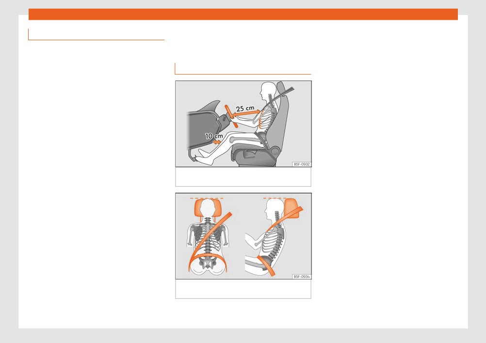
● Adjust the seat so that there is a distance of
● adjustable steering column.
at least 25 cm between the steering wheel
and your chest ››› Fig. 65 and so that you
The safety equipment mentioned above
can hold the steering wheel with both hands
works together to provide you and your pas-
on the outside of the ring at the 9 o'clock and
sengers with the best possible protection in
3 o'clock positions with your arms slightly
the event of an accident. However, these
bent.
safety systems can only be effective if you
and your passengers are sitting in a correct
● The adjusted steering wheel must face your
position and use this equipment properly.
chest and not your face.
Safety is everyone's business!
● Adjust the driver seat forwards or back-
wards so that you are able to press the ac-
Fig. 66 Correct belt web and head restraint
celerator, brake and clutch pedals to the floor
positions
with your knees slightly angled and the dis-
tance between your knees and the dash pan-
The correct sitting positions for the driver and
el is at least 10 cm ››› Fig. 65.
»
passengers are shown below.
49

Safety
● Adjust the height of the driver seat so that
● Short people must lower the head restraint
● Never adjust the steering wheel while the
you can easily reach the top of the steering
to the first anchorage position, even if your
vehicle is in motion. If you need to adjust
wheel.
head is below its upper edge.
the steering wheel while the vehicle is in
● Keep both feet in the footwell so that you
● Tall people must raise the head restraint
motion, stop safely and make the proper
have the vehicle under control at all times.
completely.
adjustment.
● Adjust and fasten your seat belt correctly
● Always keep your feet in the footwell while
● The adjusted steering wheel should be
facing your chest and not your face so as
››› page 53.
the vehicle is in motion.
not to hinder the driver's front airbag pro-
● Adjust and fasten your seat belt correctly
tection in the event of an accident.
Valid for the passenger:
››› page 53.
● When driving, always hold the steering
● Adjust the seat backrest to an upright posi-
wheel with both hands on the outside of the
tion so that your back rests completely
ring at the 9 o'clock and 3 o'clock positions
against it.
Adjusting the steering wheel posi-
to reduce injuries when the driver's front
● Move the front passenger seat back as far
tion
airbag deploys.
as possible for optimum protection should the
● Never hold the steering wheel at the 12
airbag deploy.
Read the additional information carefully
o'clock position or in any other manner
››› page 15.
(e.g. in the centre of the steering wheel). In
● Always keep your feet in the footwell while
such cases, if the driver's airbag deploys,
the vehicle is in motion.
Adjust the steering wheel before your trip and
you may sustain injuries to your arms,
● Adjust and fasten your seat belt correctly
only when the vehicle is stationary.
hands and head.
››› page 53.
Adjust the correct distance between the driv-
er and the steering wheel ››› Fig. 65 using the
Valid for the passengers in the rear sec-
controls on the driver seat ››› page 14.
Danger of injuries due to an incor-
tion:
rect sitting position
● Adjust the head restraint so that its upper
WARNING
edge is at the same level as the top of your
Incorrect use of the steering wheel adjust-
Number of seats
head, or as close as possible to the same lev-
ment function and an incorrect adjustment
The vehicle has a total of 4 seats: 2 front
el as the top of your head and under no cir-
of the steering wheel can result in severe or
cumstances below eye level. Keep the back
fatal injury.
seats and 2 rear seats. Each seat is equipped
with a seat belt.
of your neck as close as possible to the head
● After adjusting the steering column, push
restraint ››› Fig. 65 and ››› Fig. 66.
the lever firmly upwards to ensure the
If the seat belts are worn incorrectly or not at
steering wheel does not accidentally
all, the risk of severe injuries increases. Seat
change position while driving.
belts can provide optimal protection only if
the belt web is properly worn. Being seated in
50
Большое спасибо!
Ваше мнение очень важно для нас.
Нет комментариевНе стесняйтесь поделиться с нами вашим ценным мнением.
Текст