Seat Mii (2019 year). Manual in english — page 1

The essentials
Locking and unlocking the vehicle using
Locking and unlocking the driver
How it works
the key
door manually
● Locking: press the button ››› Fig. 2.
Unlocking and locking
● Unlocking: press the button
››› Fig. 2.
● Unlock the trunk lid: hold down the
Doors
››› Fig. 2 button for at least 1 second.
Locking and unlocking with the central
locking switch
● Locking: press the button ››› Fig. 3. None
of the doors can be opened from the outside.
The doors can be opened from the inside by
pulling the inside door handle.
Fig. 4 Driver-side door handle with lock cylin-
● Unlocking: press the button ››› Fig. 3.
der.
As a general rule, when the driver door is
Fig. 2 Remote control key: keys.
››› in Introduction on page 94
locked all other doors are locked. Unlocking
manually only opens the driver door.
››› page 94
● Unfold the key shaft if necessary
››› page 92.
page 11
›››
● Insert the key shaft into the lock cylinder to
unlock or lock the vehicle ››› Fig. 4.
Fig. 3 On the driver's door: central locking but-
ton.
10

The essentials
Locking the passenger door man-
● Remove the rubber cap to the front of the
Rear lid
door. The rubber cap is marked with a lock
ually
Fig. 5.
symbol ›››
● Unfold the key shaft if necessary
››› page 92.
● Insert the key shaft horizontally into the
opening and moved the coloured lever for-
ward ››› Fig. 6.
● Replace the rubber cap and close the door.
● Check if the door is locked.
● Have the vehicle checked by a specialised
workshop.
Fig. 7 Rear lid open: space for pulling.
Fig. 5 On the front part of the passenger door:
emergency locking, hidden behind a rubber
Note
Opening
gasket.
● Press the button on the vehicle key
The doors can be opened and unlocked in-
dividually from the inside by pulling the
››› Fig. 2 for about one second to unlock the
door handle. To open, pull the inner door
rear lid.
release lever twice ››› page 94.
● Insert the vehicle key into the lock cylinder
of the driver door and turn the key in an anti-
clockwise direction ››› page 94.
Closing
● Grab the handgrip inside the rear lid
››› Fig. 7 (arrow).
● Push the rear lid downwards until it locks in-
Fig. 6 Emergency locking of the vehicle using
to place in the lock.
the vehicle key
● Ensure that it is correctly closed by pulling
on it firmly.
»
The passenger door can be manually locked.
● Open the door.
11

The essentials
● Insert the key shaft into the rear lid opening
››› in Introduction on page 99
››› Fig. 8 and press the release lever in the di-
rection of the arrow to unlock the rear lid.
››› page 99
Bonnet
››› page 12
Manual release mechanism for the
rear lid
Fig. 8 From the trunk: emergency unlocking of
the rear lid.
Fig. 10 C: Bonnet securing rod in the bonnet.
D: Bonnet supported by the bonnet securing
rod
● If necessary, fold the rear seat bench back-
rest forward ››› page 14.
Opening the bonnet
● Remove equipment to access the inside of
The bonnet is released from inside the vehi-
the rear lid.
cle.
● Unfold the key shaft ››› page 92.
Fig. 9 A: Release lever in the footwell on the
Before opening the bonnet, make sure that
driver side B: Release lever on the bonnet
the windscreen wiper arms are in place
12

The essentials
against the windscreen ››› in Working in
Controls for the windows
Panoramic sunroof*
the engine compartment on page 194.
● Pull the release lever ››› Fig. 9
1 in the di-
rection of the arrow. The bonnet is released
from the lock carrier by a spring mechanism
››› in Working in the engine compart-
ment on page 194.
● Lift the bonnet up slightly while pressing the
release lever 2 in the direction of the arrow
to completely open the bonnet.
● Take out the bonnet support rod from its
clip in the direction of the arrow 3 and place
Fig. 11 On the driver door: buttons for front
Fig. 12 On the internal roof: turn the knob to
it in the corresponding open position 4 (ar-
electric windows.
open and close
row).
● Opening the window: press the button .
Closing the bonnet
● Closing the window: pull the button .
● Slightly lift the bonnet.
1
Window on the front left door
● Release the bonnet stay and replace it in its
2
Window on the front right door
support.
● At a height of approximately 30 cm let it fall
so it locks.
dows electrically on page 101he win-
If the bonnet does not close, do not press
downwards. Open it again and let it fall as
Fig. 13 On the internal roof: press or pull the
mentioned above.
knob to raise the sunroof and close it.
To raise the sliding/tilting sunroof, the knob
p›a
tment on page 193
must be in the basic position
1 .
››› page 193
● Open: turn the switch to position ››› Fig. 12
3 .
»
13
The essentials
● Comfort position: turn the switch to position
Seat belt adjustment
Before driving
››› Fig. 12
2 .
● Close: turn the switch to position ››› Fig. 12
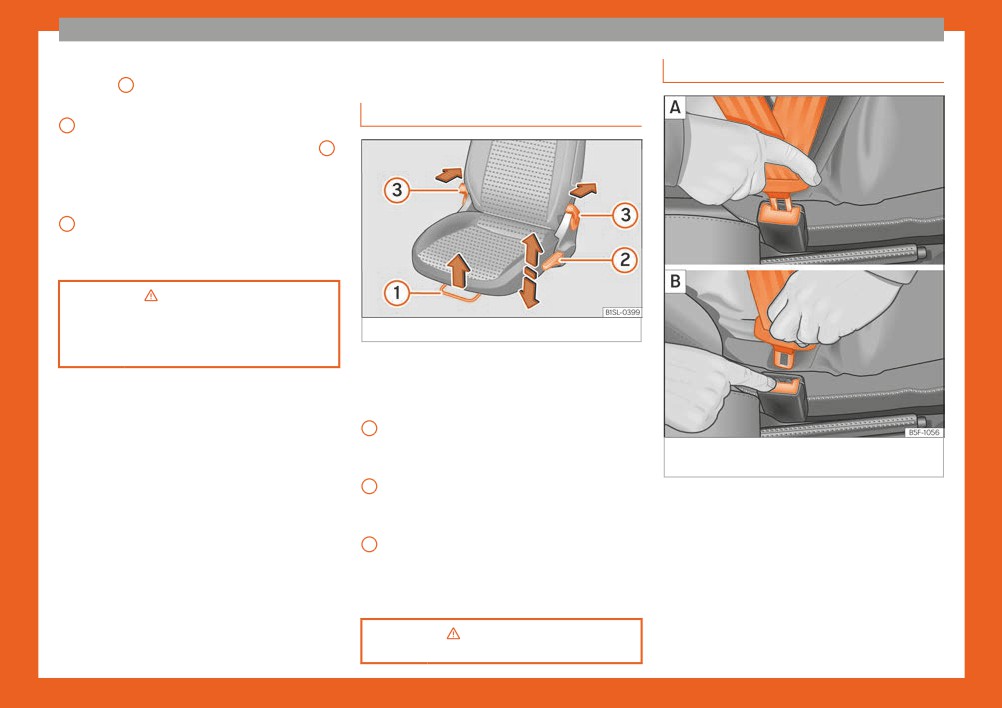
Manually adjusting the seats
1 .
● Lift: Push the switch to position ››› Fig. 13 4 .
For an intermediate position, hold down the
switch until you reach the desired position.
● Lower: pull the switch to position ››› Fig. 13
5 . For an intermediate position, hold down
the switch until you reach the desired posi-
tion.
›››
in Opening and closing the
panoramic sunroof on page 102
Fig. 14 Front left seat controls
››› page 102
The front seat head restraints are integrated
in the backrests and adjusting them is not
possible.
1
Forwards/backwards: pull the lever and
move the seat. The front seat must be en-
Fig. 15
Positioning and removing the seat belt
gaged when the lever is released!
buckle.
2
Raise/lower: pull the lever up or push
down (several times if necessary) from its
home position.
Tilt backrest: pull the lever and adjust
3
the backrest seat angle until you reach
the desired position. The seat backrest
must be engaged.
ment on page 112ont seat adjust-
14

The essentials
Seat belt tensioners
left) and the passenger side (R, right) to
the direction desired.
During a head-on, lateral or rear collision, the
Depending on the equipment fitted on
seat belts on the front seats tighten automati-
the vehicle, the mirrors may be heated
cally.
according to the outside temperature.
The tensioner can be triggered only once.
››› in Exterior mirrors on page 111
te›
sion devices on page 59
››› page 111
Fig. 16 Correct seat belt and head restraint
››› page 59
positions, viewed from front and the side.
To adjust the seat belt around your shoulders,
Adjusting the steering wheel
adjust the height of the seats.
Adjusting the exterior mirrors
The shoulder part of the seat belt should be
well centred over it, never over the neck. The
seat belt lies flat and fits comfortably on the
upper part of the body.
The lap part of the seat belt lies across the
pelvis, never across the stomach. The seat
belt lies flat and fits comfortably on the pel-
vis.
››› in Introduction on page 53
Fig. 17 On the driver door: rotating control for
Fig. 18 Mechanical steering wheel adjustment
electric windows.
››› page 57
● Push the lever ››› Fig. 18
1 downwards.
Adjusting the exterior mirrors: Turn the knob to
the corresponding position:
● Adjust the steering wheel so that you can
hold onto the steering wheel with both hands
L/R
Turning the knob to the desired position,
on the outside of the ring at the 9 o'clock and »
adjust the mirrors on the driver side (L,
15

The essentials
3 o'clock positions and your arms slightly
Airbags
bent.
● Firmly push the lever upwards as far as it
Front airbags
will go ››› in Adjusting the steering wheel
position on page 50.
p›o
tion on page 50
››› page 50
Fig. 20 Location and deployment area of the
front airbag for the passenger.
In conjunction with the seat belts, the front
airbag system gives the driver and the front
passenger additional protection for the head
Fig. 19 Location and deployment area of the
and chest in the event of a severe frontal col-
front airbag for the driver.
lision. Always remain as far away as possible
from the front airbag ››› page 49. This
16

The essentials
way, in the event of an accident, the front air-
Disabling the front passenger front
›››
in Manual disabling and ena-
bags can deploy fully when triggered, provid-
bling of the front passenger front air-
airbag
ing maximum protection.
bag with the key switch on page 65
The front airbag for the driver is located in the
››› page 64
steering wheel ››› Fig. 19 and the airbag for
the front passenger is located in the dash
panel ››› Fig. 20. Airbags are identified by the
word “AIRBAG”.
When the front airbags are triggered they fill
the zones marked in red ››› Fig. 19 and
››› Fig. 20 (radius of action). Therefore, ob-
jects should never be placed or mounted in
these areas ››› in Front airbags on
Fig. 21 On the passenger side: switch to acti-
page 63, Factory-fitted accessories are out-
vate and deactivate the front passenger air-
side the range of the front airbag for the driv-
bag.
er and the front passenger, e.g. the baseplate
for the mobile phone support.
The front passenger front airbag must be
The airbag covers fold out of the steering
disabled when a rear-facing child seat is
wheel ››› Fig. 19 and the dash panel
mounted.
››› Fig. 20 when the driver and front passen-
ger airbags, respectively, are triggered.
Disabling the front passenger front airbag
● Switch the ignition off.
● Open the door on the front passenger side.
››› in Front airbags on page 63
● Unfold the vehicle key blade
››› page 92.
● Using the vehicle key, turn the key switch to
OFF ››› Fig. 21.
● Close the door on the front passenger side.
● The control lamp on
the dash panel will remain lit while the ignition
is switched on ››› page 64.
17

The essentials
Side airbags
seat backrests ››› Fig. 22. Their position is in-
dicated by the word “AIRBAG”. The area
marked in red ››› Fig. 23 indicates the side air-
bag deployment zone.
In the event of a side-on collision, the side air-
bag will deploy in the side of the vehicle af-
fected ››› Fig. 23, thus reducing the risk of in-
juries to passengers on the side of the body
and the head facing the accident side.
Fig. 25 On the rear frame of the passenger
side door: adhesive in relation to the airbag.
››› in Side airbags* on page 63
Fig. 22 On the front seat side: location of side
A sticker with important information about the
airbag.
passenger airbag is located on the passeng-
er's sun visor and/or on the passenger side
Child seats
door frame.
Important information regarding
ding the front passenger's airbag
the front passenger's airbag
g›a
on page 66
››› page 65
Fig. 23 On the left side of the vehicle: side air-
bag deployment zone.
The side airbags are located in the outer
cushion of the driver and front passenger
Fig. 24 Passenger side sun blind.
18

The essentials
Mounting systems
Fig. 26 On rear seats: possible assemblies of chil-
dren seats.
Always secure child seats properly and safe-
Specific mounting systems for each coun-
Securing child seats with the seat
ly in the vehicle according to the child seat
try
belt
manufacturer's installation instructions.
Attachment variants ››› Fig. 26:
Mounted child seats must rest correctly on
The seat belt may be used to secure child
A
Europe: ISOFIX retaining rings and upper
the vehicle's seat and must not move or rock
seats with the universal marking (on the or-
retaining strap ››› page 20 and
more than 2.5 cm.
ange label) to the vehicle seats marked with
››› page 21.
a u in the table below.
Child seats equipped for a Top Tether strap
B
Three-point seat belt and upper retaining
must also be secured using the Top Tether re-
strap ››› page 19.
Front pas-
taining strap in the vehicle ››› page 21. At-
Category
Rear seats
sengera)
tach the retaining strap to the corresponding
The systems include the child restraint
retaining rings only. Not all rings can be used
system mounting with an upper retaining
Group 0
u
u
with the Top Tether system. Always tighten
strap (Top Tether) and lower anchoring
Up to 10 kg
points on the seat.
the Top Tether retaining strap so that the child
Category 0+
seat fits snugly against the corresponding
u
u
Up to 13 kg
seat in the vehicle.
Group 1
u
u
»
9 to 18 kg
19

The essentials
Removing the child seat
Summary chart for assembly with the ISO-
Front pas-
Category
Rear seats
FIX system
sengera)
The seat belt must not be unfastened until the
vehicle has come to a standstill.
The following table shows the assembly pos-
Group 2
u
u
sibilities for ISOFIX or i-Size child seats on the
15 to 25 kg
● Press the red button on the buckle. The
ISOFIX anchorage points of the different vehi-
Group 3
latch plate is released from the buckle.
cle seats.
u
u
22 to 36 kg
● Guide the belt back by hand so that it rolls
up easily and the trim will not be damaged.
Class
a) Compliance with current national legislation and
Front
the manufacturer's instructions is required when using
● Remove the child seat from the vehicle.
Age
accord-
Rear
passen-
or installing child seats.
group
ing to
seats
ger seat
›››
in Safety instructions on
sizea)
Securing the child seat using the seat belt
page 67
Group 0:
E
X
IL-SU
● Please read and observe the child seat
up to 10 kg
manufacturer's handling instructions.
E
X
● Move the front passenger seat, or the rear
Fixing the child seat with the ISOFIX
Group 0+:
seat bench back as far as possible and, in the
D
X
IL-SU
system
up to 13 kg
case of an adjustable backrest, set it in the
C
X
upright position ››› page 49.
D
X
● Positioning the child seat on the seat ac-
cording to the manufacturer's instructions.
C
X
● Fasten the seat belt or pass it around the
Group 1:
IL-SU
B
X
child seat structure in the manner described
9 to 18 kg
IUF
in the manufacturer's instructions.
B1
X
● Make sure the seat belt is not twisted.
A
X
● Insert the latch plate into the buckle for the
Group 2:
appropriate seat and push it down until it is
-
X
IL-SU
15 to 25 kg
securely locked with an audible click.
Fig. 27 On the seat of the vehicle: identifica-
Group 3:
● Ensure that the upper belt web lies tightly
tion variants of the anchor points for the child
-
X
IL-SU
22 to 36 kg
on the child seat.
seats
● Pull the belt (it must be no longer possible
Both outermost rear seats have two retainers
to pull the lower belt webbing out).
named lower anchor points.
20

The essentials
● Observe the manufacturer's instructions
Securing a child seat with the Top
Class
Front
when installing and removing the child seat
Age
accord-
Rear
Tether retaining strap
passen-
››› in Safety instructions on page 67.
group
ing to
seats
ger seat
sizea)
● Press the child seat onto the retaining rings
››› Fig. 27 in the direction of the arrow. The
i-Size
child seat must be safely engaged and click
child re-
-
X
X
audibly into place.
straint
system
● Pull on both sides of the child seat to ensure
that it is secure.
X: seat not suitable for an ISOFIX or i-Size child seat
of this group.
IL-SU: seat suitable for an ISOFIX child seat with
Child seat with adjustable retaining straps
semi-universal certification. Take into account the list
● Observe the manufacturer's instructions
of vehicles of the manufacturer of the child seat.
IUF: seat suitable for an ISOFIX child seat with univer-
when installing and removing the child seat
Fig. 28 Example of an upper retaining strap
sal certification.
››› in Safety instructions on page 67.
connected.
● Place the child seat on the seat cushion
a) The indication of class according to size corre-
sponds to the authorised bodyweight for the child
and attach the retaining strap hooks to the
● Observe the manufacturer's instructions
seat. In child seats with universal or semi-universal
retaining rings ››› Fig. 27.
when installing and removing the child seat
approval, the class according to size is indicated on
● Tighten the straps evenly using the corre-
››› in Safety instructions on page 67.
the ECE approval label. The indication of class ac-
cording to size is stated on the corresponding child
sponding adjustment device. The child seat
● Unlock the seat backrest and fold it gently
seat.
must sit flush against the vehicle seat.
forward ››› page 14.
● Pull on both sides of the child seat to ensure
● Remove the head restraints situated behind
Child seats with rigid mounting
that it is secure.
the child seat and store them safely in the ve-
For the installation of a child seat with rigid
hicle ››› page 49.
mounting auxiliary introduction elements can
● Guide the upper retaining strap from of the
page 67Safety instructions on
be used. These elements facilitate fitting and
child seat back to the luggage compartment,
protect the upholstery. They form part of the
feeding it through the seat backrest and the
supply volume of the child seat or can be ac-
rear shelf.
quired at a SEAT dealership. If necessary,
● Fold back the seat backrest and push it
these elements are inserted in both anchor
firmly into the lock.
points of the vehicle ››› in Safety instruc-
● Secure the child seat to the lower anchor
tions on page 67.
points ››› page 20
»
21
The essentials
● Hook the upper retaining strap in the lug-
locks. In vehicles with automatic transmission,
gage compartment, to the corresponding re-
in order to remove the key, move the gear
s
tarting the engine on page 149
taining ring ››› Fig. 28.
shift to the N position. If necessary, press the
gear shift blocking key and release it.
● Tighten the strap so that the top of the child
››› page 149
seat rests on the seat backrest.
● Unlock the steering wheel: put the key into
the ignition and turn it at the same time as the
steering wheel in the direction indicated by
p›age
67
the arrow. If it is not possible to turn the steer-
Lights and visibility
ing wheel, it may be because it is locked.
Light switch
Turning on/switching off the ignition, glow
Starting the vehicle
plugs reheating
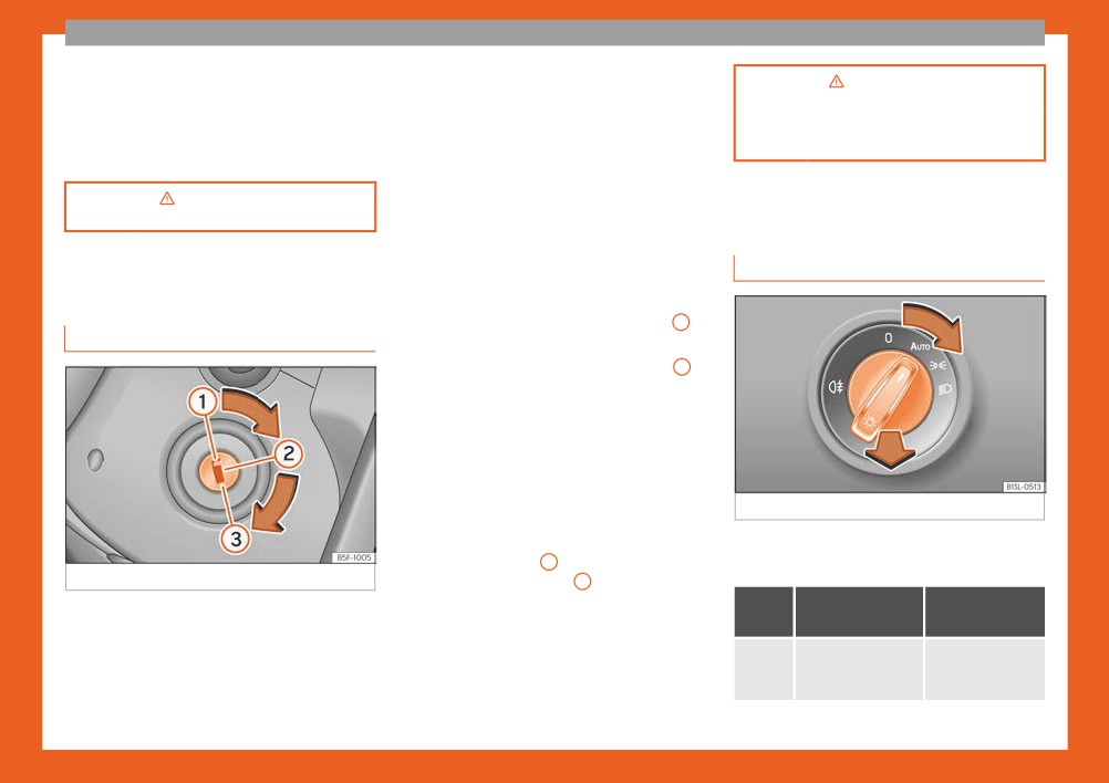
● Turn on the ignition: turn the key to the 2
Ignition lock
position.
● Turn off the ignition: turn the key to the
1
position.
Starting the engine
● Manual transmission: press the clutch ped-
al all the way down and move the gearbox
lever into neutral.
Fig. 30 Instrument console: light panel.
● Automatic transmission: press the brake
pedal and move the selector lever to N.
Turn the switch to the required position
● Turn the key to the 3 position. The key au-
››› Fig. 30.
Fig. 29 Ignition key positions.
tomatically returns to the 2 position. Do not
press the accelerator.
Sym-
Ignition switch-
Ignition is
Turn on the ignition: place the key in the igni-
bol
ed off
switched on
tion and start the engine.
Start-Stop system*
Fog lights, dipped
Light off or day-
When you stop and release the clutch pedal,
beam and side
time driving light
Locking and unlocking the steering wheel
the Start-Stop system* turns off the engine.
lights off.
on.
● Lock the steering wheel: remove the key
The ignition remains switched on.
from the ignition and turn the wheel until it
22
The essentials
Sym-
Ignition switch-
Ignition is
Turn signal and main beam lever
Hazard warning lights
bol
ed off
switched on
The “Coming
Automatic control
home” and “Leaving
of dipped beam
home” guide lights
and daytime run-
may be switched
ning light.
on.
Side light on.
Dipped beam head-
Dipped beam
light off
switched on.
Rear fog light: move the switch com-
Fig. 31 Turn signal and main beam lever in
Fig. 32 Dashboard: switch for hazard warning
pletely from positions , or .
their initial position
lights.
Turn on fog lights: push the switch or turn it to
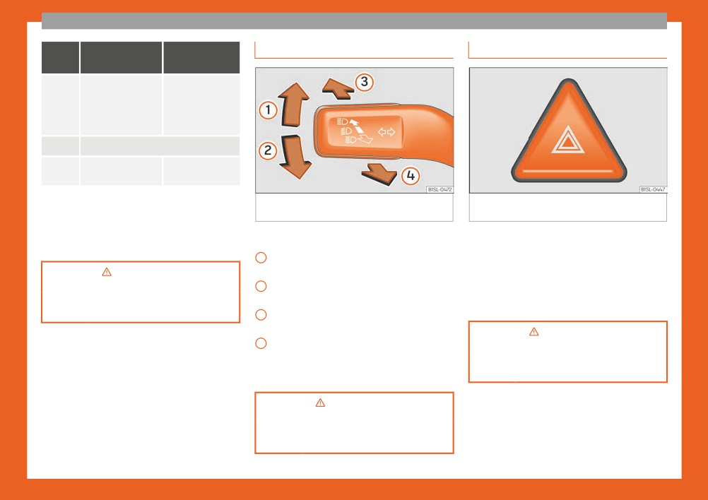
More the lever to the required position:
Switched on, for example:
the position.
1
Right turn light: right-hand parking light
● When approaching a traffic jam
(ignition switched off).
● In an emergency
p›age
104
2
Left turn light: left-hand parking light (ig-
● The vehicle has broken down
nition switched off).
● When towing or being towed
››› page 103
3
Main beam on: control lamp lit up on
the instrument panel.
4
Light flash: on with the lever pushed. Con-
p›age
106
trol lamp lit up.
››› page 106
Lever all the way down to switch it off.
lever on page 105
››› page 105
23
The essentials
Interior lights
Windscreen wipers and window
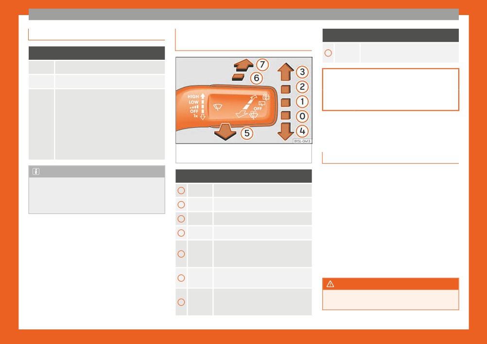
More the lever to the required position:
wiper blade
Automatic wipe for cleaning rear win-
Position: Function
7
dows with the lever pressed.
Switching off the reading light.
Switching on the reading light.
››› page 108
Switches door contact control on (central
position).
››› page 46
The reading light comes on automatically
when the vehicle is unlocked, a door is
opened or the key is removed from the ig-
nition.
The light goes off a few seconds after all
SEAT information system
the doors are closed, the vehicle is locked
Fig. 33 Operating the windscreen wiper and
or the ignition is switched on.
rear wiper.
Introduction
Note
With the ignition switched on it is possible to
More the lever to the required position:
The reading lights go out when the vehicle
access different messages via the display on
is locked, or a few minutes after the key is
0
Windscreen wipers off.
the instrument panel display.
removed from the ignition. This prevents
1
Windscreen interval wipe.
The number of messages displayed on the in-
the vehicle's battery from discharging.
strument panel display will vary according to
2
Slow wipe.
the vehicle electronics and equipment.
3
Continuous wipe.
A specialised workshop will be able to pro-
gramme or modify additional functions, ac-
Brief wipe - short wipe. Hold the lever
cording to the vehicle equipment. SEAT rec-
4
down for more time to increase the
wipe frequency.
ommends taking your car in for technical
service.
Automatic wipe for cleaning wind-
5
screens with the lever up.
WARNING
Interval wipe for rear window. The
Any distraction may lead to an accident,
6
wiper will wipe the window approxi-
with the risk of injury.
mately every six seconds.
24

The essentials
● Do not consult the messages on the in-
Multifunction display (MFI)
Possible displays
strument panel screen when driving.
Menu
Function
The multifunction display (MFD) has two au-
tomatic memories: 1 - Partial memory and 2
Current time in hours (h) and mi-
Time
- Total memory. The selected memory will
nutes (min).
Management of indications on the
be shown in the lower right-hand corner of
display
the display.
Travelling
This indicates the hours (h) and mi-
nutes (min) since the ignition was
time
switched on.
With the ignition switched on, and memo-
ry 1 or 2 displayed, briefly press OK to
The current fuel consumption dis-
Current
play operates throughout the jour-
change from one memory to another.
fuel con-
ney, in l/100 km; with the engine
The memory stores the values for the
sumption
running and the vehicle stopped, in
journey and the consumption from the
l/hour.
moment the ignition is switched on un-
After turning on the ignition, aver-
til it is switched off again.
age fuel consumption in li-
Trip memo-
If the journey is broken for more than 2
tres/100 km will be displayed after
ry (for a sin-
hours, the memory is automatically
Average
travelling about 100 metres. Oth-
gle jour-
erased. If the journey is continued in
fuel con-
erwise horizontal lines are dis-
ney).
less than 2 hours after the ignition is
sumption
Fig. 34 Windscreen wipers lever: control but-
played. The value shown is upda-
switched off, the new data is added to
tons.
ted approximately every 5 sec-
the data already stored in the memo-
onds.
ry.
Calling up options
Approximate distance in km that
The memory stores the values of any
● Switch the ignition on.
can still be travelled with the fuel
number of journeys, until it counts a
Operating
remaining in the tank, assuming
● If a message or vehicle symbol is displayed,
total of 19 hours and 59 minutes of
range
the same style of driving is main-
driving, or 1999.9 km or miles of driv-
press OK/RESET (››› Fig. 34 A ).
tained. This is calculated using the
Total mem-
ing, depending on the type of instru-
ory (for all
current fuel consumption.
● Press the top or bottom part of the rocker
ment panel fitted. On reaching either
switch ››› Fig. 34 B until the desired option
journeys).
of these limits, the memory is auto-
Distance
Distance travelled, after ignition is
appears.
matically erased and starts to count
covered
switched on, in km.
»
from 0 again.
25
The essentials
lever or or buttons on the multifunction
● Switching on the CCS: Move switch
Menu
Function
steering wheel for 5 seconds. Next, press OK
››› Fig. 35
1 to . The system is on. If no
The average speed will be shown
again or wait a few seconds. The speed is
speed has been programmed, the system will
after a distance of about 100 me-
stored and the warning activated.
not control it.
Average
tres has been travelled. Otherwise
speed
horizontal lines are displayed. The
● To switch off, press OK . The stored speed is
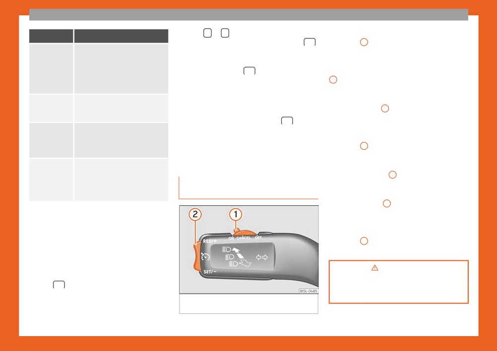
● Activate the CCS: Press button ››› Fig. 35
value shown is updated approxi-
deleted.
2 in the area. The current speed is
mately every 5 seconds.
memorised and controlled.
Digital
Current speed displayed digitally.
Manually erasing memory 1 or 2
● Temporarily switching off the CCS: Move
display of
● Select the memory to be erased.
switch ››› Fig. 35
1 to or push the
speed
brake. The cruise control system is switched
● Press and hold the eject button OK for ap-
off temporarily.
Digital
Digital display of the current tem-
proximately 2 seconds.
coolant
perature of the engine liquid cool-
● Reactivating the CCS: Press button
tempera-
ant.
››› Fig. 35
2 in . The memorised speed is
ture gauge
saved and controlled again.
If the stored speed is exceeded
Cruise control
● Increasing stored speed during CCS regu-
(between 30 - 250 km/h, or 18 -
Warning at
lation: press button
2 in . The vehicle
--- km/h
155 mph), an audible warning is
Operating the cruise control sys-
accelerates until the new stored speed.
given together with a visual warn-
ing.
tem (CCS)*
● Reducing stored speed during CCS regula-
tion: press button 2 in to lower the
Changing between display modes
speed by 1 km/h (1 mph). Speed is reduced
until reaching the new stored speed.
● Press the rocker switch in the windscreen
● Switching off the CCS: Move switch
wiper lever.
››› Fig. 35
1 to . The system is disconnec-
ted and the memorised speed is deleted.
Storing a speed for the speed warning
● Select the display Speed warning at
--- km/h.
p›age
172
● Press OK on the windscreen wiper lever to
store the current speed and switch off the
››› page 171
warning.
Fig. 35 Switch and controls for operating the
CCS.
● In addition, set the required speed by press-
ing the rocker switch on the windscreen wiper
26
The essentials
Warning lamps
Fault in Traction Control* or discon-
City Safety Assist switched on manual-
nection caused by the system; OR
ly ››› page 175.
Traction Control* in operation
Control and warning lamps
››› page 156.
City Safety Assist switched off manual-
ly ››› page 175.
The control and warning lamps are indicators
Fault in the ABS ››› page 156.
Service interval display ››› page 90.
of warnings, ›››
, faults ››› or certain func-
Rear fog light switched on
tions. Some control and warning lamps come
››› page 103.
Start-Stop system activated
on when the ignition is switched on, and
››› page 170.
switch off when the engine starts running, or
Fault in the emission control system
››› page 168.
Start-Stop system unavailable
while driving.
››› page 170.
When certain control and warning lamps are
Fault in the petrol engine management
lit, an audible warning is also heard.
››› page 168.
WARNING
Fuel tank almost empty ›››page 190.
If the warning lamps are ignored, the vehi-
Handbrake ››› page 152.
cle may stall in traffic, or may cause acci-
Natural gas tank is almost empty
dents and severe injuries.
Fault in the brake system ››› page 152.
››› page 190.
● Never ignore the warning lamps.
Engine cooling fluid ››› page 198.
Fault in airbag system and seat belt
● Stop the vehicle safely as soon as possi-
tensioners ››› page 64.
Engine oil pressure ››› page 195.
ble.
Tyre monitor system ››› page 212.
● Park the vehicle away from traffic and
Fault in the steering system
ensure that there are no highly flammable
››› page 164.
Turn lights or emergency lights on
››› page 103.
materials under the vehicle that could
Driver or passenger has not fastened
come into contact with the exhaust system
seat belt ››› page 54.
Cruise control ››› page 171.
(e.g. dry grass, fuel).
Fault in the generator ››› page 203;
Main beam on or flasher on
● A faulty vehicle represents a risk of acci-
dent for the driver and for other road users.
OR the Start-Stop system cannot start
››› page 103.
the engine ››› page 170.
If necessary, switch on the hazard warning
A passenger in the rear seats has fas-
lamps and put out the warning triangle to
Fault in ESC or disconnection caused
tened their seat belt ››› page 54.
advise other drivers.
by the system; OR ESC or ASR in oper-
ation ››› page 156.
A passenger in the rear seats has not
● Before opening the bonnet, switch off the
fastened their seat belt ››› page 54.
engine and allow it to cool.
»
City Safety Assist ››› page 175.
27

The essentials
● In any vehicle, the engine compartment is
The position of each of the gears is shown on
Automatic gearbox
a hazardous area and could cause severe
the gear stick ››› Fig. 36.
injuries ››› page 193.
● Keep the clutch pedal pushed all the way
down.
CAUTION
● Move the gearbox lever to the required po-
Failure to heed the warning lamps when
sition ››› in Manual gear change on
they appear may result in faults in the vehi-
page 159.
cle.
● Release the clutch pedal to engage clutch.
Selecting reverse gear
Gearbox lever
● Engage reverse gear only when the vehicle
is stopped.
Fig. 37 Automatic gearbox diagram of gears
Manual gearbox
● Keep the clutch pedal pushed all the way
R
Reverse gear
down ››› in Manual gear change on
N
Neutral (idling)
page 159.
D
Drive (forward)
● Place the gearbox lever into neutral and
push the lever downwards.
M
Tiptronic mode: pull the lever forwards
(+) to go up a gear or backwards (-) to
● Slide the gearbox lever to the right, and
go down a gear.
then backward as shown on the lever.
● Release the clutch pedal to engage clutch.
p›age
160
p›age
159
››› page 160
Fig. 36 Gear shift pattern of a 5-speed man-
ual gearbox
››› page 159
28
The essentials
Air conditioning
How does the Climatronic* work?
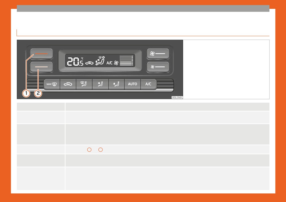
Fig. 38 In the centre console, top section: Clima-
tronic control panel.
Switching off
Switch the system off by pressing several times on the lower button ››› Fig. 38
Cooling mode
The button switches cooling mode on and off.
Automatic mode
The button switches the automatic mode on and off. The automatic mode maintains temperature constant in the vehicle’s interior.
Temperature and the amount and distribution of air are controlled automatically. Modifying ventilation automatically switches off the auto-
matic mode.
Temperature
Press buttons
1 and 2 ››› Fig. 38 to adjust the temperature. The adjusted temperature is displayed on the screen.
Fan
The ››› Fig. 38 buttons are used to adjust fan speed.
: The air is distributed towards the upper part of the body through the dash panel air vents.
Air distribution
: Air distribution to footwells
: Air distribution to the windscreen
»
29
Большое спасибо!
Ваше мнение очень важно для нас.
Нет комментариевНе стесняйтесь поделиться с нами вашим ценным мнением.
Текст