Chrysler Le Baron, Dodge Dynasty, Plymouth Acclaim. Manual — part 135
41TE ON-BOARD DIAGNOSTICS
INDEX
page
page
CCD Bus
. . . . . . . . . . . . . . . . . . . . . . . . . . . . . . 145
Diagnostic Trouble Code Charts
. . . . . . . . . . . . 146
Diagnostic Trouble Codes
. . . . . . . . . . . . . . . . . 145
DRB II Scan Tool
. . . . . . . . . . . . . . . . . . . . . . . 146
General Information
. . . . . . . . . . . . . . . . . . . . . . 145
Limp-In Mode
. . . . . . . . . . . . . . . . . . . . . . . . . . 145
On-Board Diagnostics Information
. . . . . . . . . . . 145
GENERAL INFORMATION
The information in this manual is designed to help
the technician understand and repair the transaxle
with the aid of the built in on-board diagnostics.
Chrysler Corporation has developed a com-
plete set of diagnostic manuals which cover the
diagnosis of the 41TE transaxle. They have been
designed to make transaxle diagnosis accurate
and simple. Use these manuals with the DRB II
scan tool and the latest cartridge, when diagnos-
ing transaxle problems.
ON-BOARD DIAGNOSTICS INFORMATION
The 41TE transaxle is controlled and monitored by
the transmission control module. The transmission
control module monitors critical input and output
circuits within the transaxle.
Some circuits are tested continuously; others are
checked only under certain conditions. Each circuit
monitored by the transmission control module has a
corresponding fault message assigned to it that can be
read with the DRB II scan tool.
If the on-board diagnostic system senses that one of
the circuits is malfunctioning, the corresponding code
is stored in memory. If the malfunction goes away after
the code is stored, the transmission control module will
erase the code after 75 key cycles.
CCD BUS
In order to diagnose the 41TE transaxle, diagnostic
trouble codes in the transmission control module’s
memory should be read. Use the Diagnostic Readout
Box (DRB II) scan tool to read codes. If more than one
diagnostic trouble code exists, diagnostic priority
should be given to the most recent code. With CCD bus
bias and communication problems, the DRB II scan
tool displays an appropriate message. Diagnostic
trouble codes might not be accessible until the bus
problem is fixed. The following is a list of probable
causes for a bus problem:
• Open or short to ground/battery in either or both
CCD bus wires (pins 4 and 43).
• Open or short to ground/battery in either or both
41TE transaxle’s bias wires (pin 5 and 44) on vehicles
requiring the transaxle to bias the bus.
• Open or short to ground/battery in the diagnostic
connector bus wire.
• Internal failure of any module connected to the bus.
The CCD bus should have 2.5 volts (+2.5 volts on
CCD+ and -2.5 volts on CCD-).
The bus error message displayed by the DRB II scan
tool should be helpful in diagnosing the CCD bus.
For more information on diagnosing CCD bus prob-
lems, refer to the 1993 Diagnostic Procedures Manual
(non-communication with the CCD bus). All other
problems refer to the 1993 Body Vehicle Communica-
tions Diagnostic Procedures Manual.
DIAGNOSTIC TROUBLE CODES
Diagnostic Trouble Codes are two-digit numbers that
identify which circuit is malfunctioning. A code can be
set for hydraulic and mechanical reasons as well as for
electrical problems. In most cases, codes do not pin-
point which specific component is defective.
Diagnostic trouble codes can only be read with
the use of the DRB II scan tool or equivalent.
HARD FAULTS
Any Diagnostic trouble code that comes back within
3 engine starts (reset count 3 or less) is a ‘‘Hard Fault’’.
This means that the defect is there every time the
transmission control module checks that circuit.
SOFT FAULTS
A ‘‘Soft Fault’’ is one that occurs intermittently. It is
not there every time the transmission control module
checks the circuit. Most soft faults are caused by wiring
or connector problems. Intermittent defects must be
looked for under the specific conditions that caused
them.
LIMP-IN MODE
The
transmission
control
module
continuously
checks for electrical and internal transaxle problems.
When a problem is sensed, the transmission control
module stores a diagnostic trouble code. All but twelve
of these codes cause the transaxle to go into the
‘‘Limp-in mode’’. While in this mode, electrical power is
taken away from the transaxle. When this happens,
the only transaxle ranges that will function are:
Ä
TRANSAXLE
21 - 145
• Park
• Neutral
• Reverse
• Second Gear
No upshifts or downshifts are allowed while in the
Limp-in mode. The position of the manual valve
alone allows the three ranges that are available.
Although engine performance will be reduced while
in this mode, the vehicle can be driven in for service.
DRB II SCAN TOOL
The DRB II scan tool is a diagnostic read-out box
designed by Chrysler to gain access to the on-board
diagnostics. These on-board diagnostics are found on
all Chrysler-built cars and trucks.
The DRB II scan tool has a few diagnostic capabil-
ities by itself. To perform most diagnostic tests, a
program cartridge must be inserted. It contains the
diagnostic test programs.
There are scan tools available from other manufac-
tures that can be used on Chrysler vehicles. How-
ever, the diagnostic test procedures in this manual
have been designed for use with the Chrysler’s DRB
II scan tool.
The DRB II scan tool operates by communicating
with the module of the vehicle system being tested.
To communicate with the transmission control mod-
ule, the DRB II scan tool must be connected to the
blue CCD bus connector located under the instru-
ment panel. Refer to the ‘‘Using the DRB II Scan
Tool’’ manual or the Diagnostic Procedures Manual
for information on how to use the DRB II scan tool.
DIAGNOSTIC TROUBLE CODE CHARTS
Below is a brief description of what each section of
the diagnostic trouble code charts are addressing.
• DIAGNOSTIC TROUBLE CODE-Tells the code
number and name (as shown on the DRB II scan
tool).
• BACKGROUND-A brief description of the circuit
that the transmission control module is monitoring.
• WHEN CHECKED-The point of time or condition
when the transmission control module makes it’s sys-
tem check.
• ARMING CONDITIONS-The parameters that
must be met before a code can be set.
• FAULT CONDITION-What the transmission con-
trol module saw that is determined to be a problem.
(ie. voltage to high or low, switch/solenoid problems)
• FAULT SET TIME-Refers to the amount of time
(in seconds) a failure must occur before a diagnostic
trouble code is set in memory.
• EFFECT-Refers to how the fault effects transaxle
operations.
• POSSIBLE CAUSE-Refers to the systems or cir-
cuits which could cause the fault to be recorded.
21 - 146
TRANSAXLE
Ä
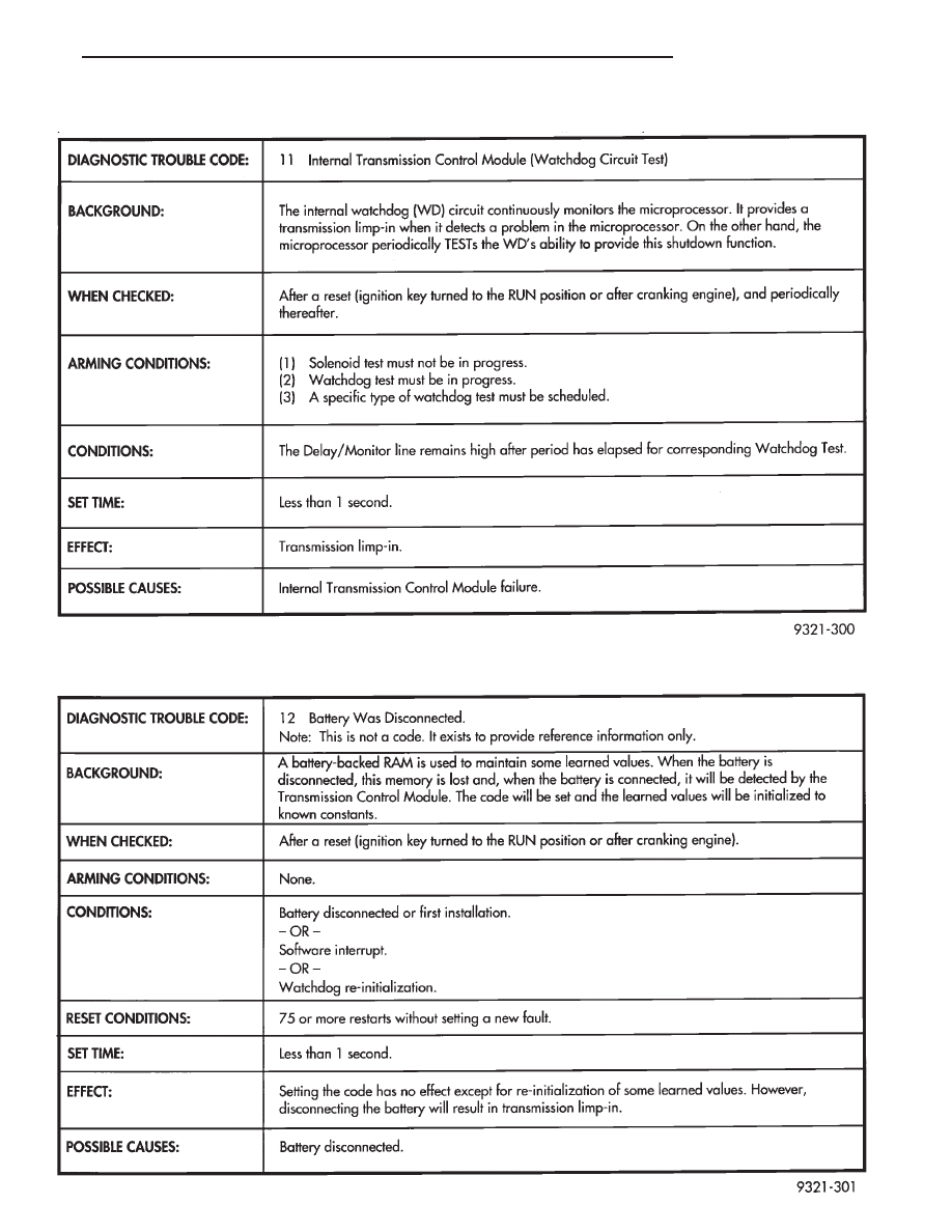
DIAGNOSTIC TROUBLE CODE 11
DIAGNOSTIC TROUBLE CODE 12
Ä
TRANSAXLE
21 - 147
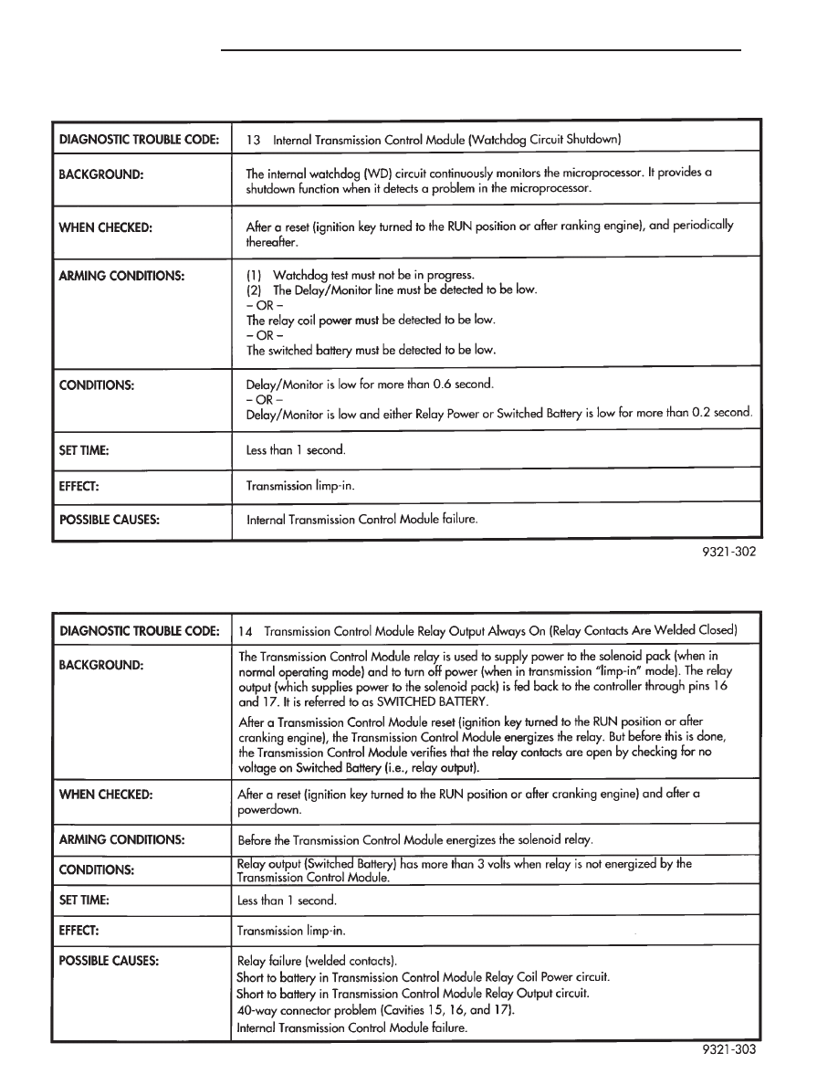
DIAGNOSTIC TROUBLE CODE 13
DIAGNOSTIC TROUBLE CODE 14
21 - 148
TRANSAXLE
Ä
Нет комментариевНе стесняйтесь поделиться с нами вашим ценным мнением.
Текст