Chrysler Le Baron, Dodge Dynasty, Plymouth Acclaim. Manual — part 300
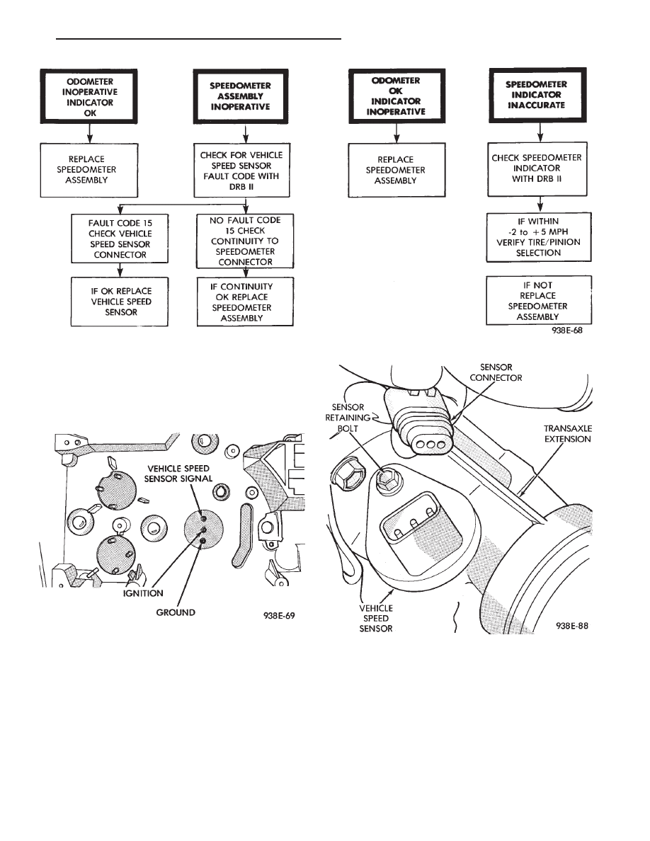
SPEEDOMETER CIRCUIT TESTING
(1) Remove speedometer from cluster.
(2) With ignition switch in the ON position, check
for battery voltage across ignition and ground pins
(Fig. 28).
(3) Check continuity from vehicle speed sensor sig-
nal pin to connector at vehicle speed sensor.
(4) Test for faulty vehicle speed sensor.
(5) If all of these tests prove good, replace speed-
ometer.
VEHICLE SPEED SENSOR REPLACEMENT
(1) Remove harness connector from sensor and
make sure weather seal is on harness connector (Fig.
29).
(2) Remove sensor retaining bolt.
(3) Pull sensor and pinion gear assembly out of
transaxle. If necessary, carefully pry loose with a flat
blade screwdriver (Fig. 30).
(4) Remove pinion gear from sensor.
(5) For installation reverse above procedures and
seat sensor assembly by hand to insure proper gear
engagement. Tighten retaining bolt to 7 N
Im (60 in.
lbs.) torque.
Fig. 27 Speedometer Diagnosis
Fig. 28 Speedometer Pins
Fig. 29 Vehicle Speed Sensor and Connector
Ä
INSTRUMENT PANEL AND GAUGES
8E - 11

ELECTRONIC AUTOMATIC TRANSAXLE
VEHICLE SPEED SENSOR REPLACEMENT
The output vehicle speed sensor is located to the
left of the manual shift lever.
(1) Raise and support vehicle on safety stands.
(2) Remove vehicle speed sensor (Fig. 31).
(3) For installation, reverse above procedures.
VEHICLE SPEED SENSOR TEST
For testing of the vehicle speed sensor and related
components refer to the Powertrain Diagnostics Test
Procedure Manual.
TACHOMETER DRIVE MODULE
REPLACEMENT
(1) Remove cluster assembly. Refer to Cluster As-
sembly Replacement.
(2) Pull tachometer drive module from printed cir-
cuit board (Fig. 32).
(3) For installation reverse above procedures and
use care when aligning module to printed circuit
board.
LOW FUEL WARNING MODULE
REPLACEMENT
(1) Remove cluster assembly. Refer to Cluster As-
sembly Replacement.
(2) Pull low fuel relay from printed circuit board
(Fig. 32).
(3) For installation reverse above procedure. Use
care when aligning module to printed circuit board.
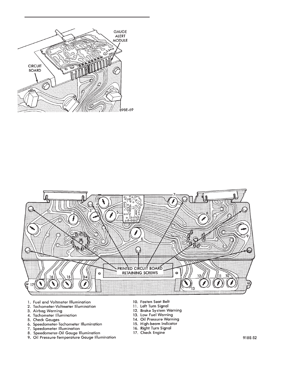
GAUGE ALERT MODULE REPLACEMENT
(1) Remove cluster assembly. Refer to Cluster As-
sembly Replacement.
(2) Pull gauge alert module from printed circuit
board (Fig. 33).
(3) For installation reverse above procedures. Use
care when aligning module to printed circuit board.
CLUSTER LAMP REPLACEMENT
(1) Remove cluster, radio and rear window defog-
ger bezels.
(2) Remove cluster. Refer to Cluster Assembly Re-
placement.
Fig. 30 Vehicle Speed Sensor and Speedometer
Pinion
Fig. 31 Vehicle Speed Sensor Removal
Fig. 32 Tachometer Drive and Low Fuel Warning
Module
8E - 12
INSTRUMENT PANEL AND GAUGES
Ä
(3) Remove lamp sockets as necessary by turning
them counterclockwise (Fig. 34 and 35).
PRINTED CIRCUIT BOARD REPLACEMENT
(1) Remove cluster assembly.
(2) Remove tachometer drive module, low fuel re-
lay and gauge alert module (Fig. 32).
(3) Remove all cluster lamps.
(4) Remove mounting screws securing printed cir-
cuit board to cluster housing (Fig. 34).
(5) For installation reverse above procedures.
ELECTRONIC CLUSTER
SELF DIAGNOSTIC SYSTEM
The electronic clusters (Fig. 36) have an internal
diagnostics routing to isolate problems within the
cluster or sending units.
Using the cluster Self-Diagnostic Test will deter-
mine whether problem is within cluster or outside of
cluster (Fig. 37 and 38).
Successful completion of the SELF DIAGNOSTIC
TEST indicates that the problem is in the connectors
or sensors outside of the module. Refer to Fig. 39 for
terminal listing.
CONDITION: CLUSTER DISPLAYS DO NOT
ILLUMINATE AFTER VEHICLE IS STARTED
PROCEDURE
(1) Check fuses and verify battery and ignition
voltage at cluster connector.
(2) Check ground from cluster connector to instru-
ment panel ground stud.
(3) Check lamps, replace if necessary.
Fig. 34 Mechanical Cluster Lamp Location
Fig. 33 Gauge Alert Module
Ä
INSTRUMENT PANEL AND GAUGES
8E - 13
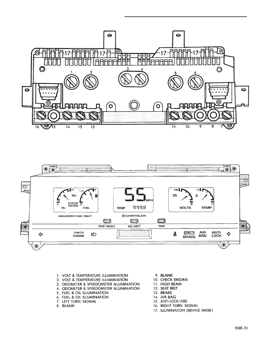
Fig. 35 Electronic Cluster Lamp Location
8E - 14
INSTRUMENT PANEL AND GAUGES
Ä
Нет комментариевНе стесняйтесь поделиться с нами вашим ценным мнением.
Текст