Chrysler Le Baron, Dodge Dynasty, Plymouth Acclaim. Manual — part 100

TRANSAXLE REMOVAL AND INSTALLATION
Transaxle removal does not require engine re-
moval.
After installing transaxle, fill transaxle to bottom of
fill plug hole with SAE 5W-30 engine oil before lower-
ing vehicle to floor.
(1) Disconnect or connect negative battery cable.
(2) Install a lifting eye on battery ground strap bolt
on left side of engine. Then install the engine support
fixture as shown in Figure 1.
(3) Disconnect or connect gearshift cables at tran-
saxle. Disconnect speedometer. Disconnect or connect
gearshift cables bracket at transaxle.
(4) Remove or install both front wheel and tire
assemblies.
(5) Remove or install left front splash shield.
(6) Remove or install engine left mount from tran-
saxle.
CAUTION:Left engine mounting bolts used in posi-
tion number 1 and number 3 are the same length. The
bolt in the number 2 position is longer. If bolt number
2 is used in position number 3 it can damage the
selector shaft housing when the bolt is seated (Fig.
2).
(7) Remove or install anti-rotational link (or anti-
hop damper) from crossmember bracket. Do not re-
move bracket from transaxle.
(8) Refer to Group 2 Suspension, to remove or
install both drive shafts.
When removing or installing the transaxle, it
may be helpful to use locating pins in place of the
top transaxle to engine bolts (Fig. 3).
Make the locating pins from two stock (transaxle
case to engine block) bolts as follows: Using a hacksaw,
remove bolt heads, cut slot in end of bolts for a screw
driver, and remove burrs with a grinding wheel.
Install the locating pins into the engine block and
proceed with transaxle installation. After transaxle is
in place, install bolts and remove locating pins before
removing transmission jack.
Fig. 1 Engine Support Fixture
Fig. 2 Left Engine Mount Bolt Location
Fig. 3 Remove or Install Bolts
Ä
TRANSAXLE
21 - 5
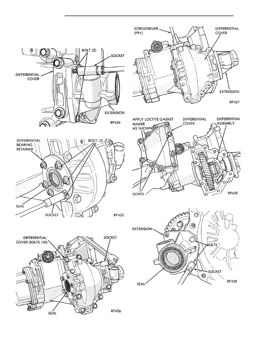
OUT OF CAR TRANSAXLE—DISASSEMBLE AND
ASSEMBLE
DIFFERENTIAL
Fig. 1 Remove or Install 2 Extension Outer Bolts
Fig. 2 Remove or Install 3 Differential Bearing
Retainer Outer Bolts
Fig. 3 Remove or Install Differential Cover Bolts
Fig. 4 Remove Differential Cover
Fig. 5 Differential Cover Removed
Fig. 6 Remove or Install 2 Extension Bolts
21 - 6
TRANSAXLE
Ä
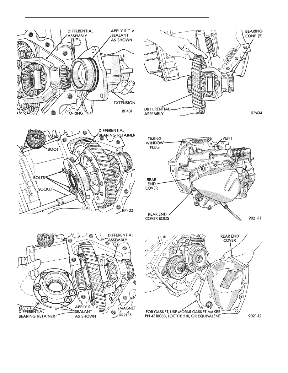
GEAR SET
CAUTION: Tool 6252 must be used to remove or in-
stall this nut. Always install a NEW nut and tighten
to 258 N
I
m (190 ft. lbs.).
Fig. 7 Remove or Install Extension
Fig. 8 Remove or Install 3 Differential Bearing
Retainer Bolts
Fig. 9 Remove or Install Differential Bearing
Retainer
Fig. 10 Differential Assembly Removed
Fig. 1 Rear End Cover Bolts
Fig. 2 Rear End Cover Removed
Ä
TRANSAXLE
21 - 7

Fig. 3 Remove 5th Fork Roll Pin
Fig. 4 Install 5th Fork Roll Pin
Fig. 5 5th Fork and Sleeve
Fig. 6 Snap Ring
Fig. 7 Remove 5th Synchronizer Hub
Fig. 8 Install 5th Synchronizer Hub
21 - 8
TRANSAXLE
Ä
Нет комментариевНе стесняйтесь поделиться с нами вашим ценным мнением.
Текст