Chrysler Le Baron, Dodge Dynasty, Plymouth Acclaim. Manual — part 98
REAR (STUB) AXLE ALIGNMENT ALL MODELS
INDEX
page
page
General Information
. . . . . . . . . . . . . . . . . . . . . . . 89
Rear Wheel Alignment
. . . . . . . . . . . . . . . . . . . . . 89
GENERAL INFORMATION
Because front wheel drive vehicles are equipped with
rear suspension incorporating stub axles (or wheel
spindles). It is possible to align both the camber and toe
of the rear wheels.
REAR WHEEL ALIGNMENT
Alignment adjustment if required. Is made by adding
0.010 inch shims (from the service package kit) be-
tween the spindle mounting surface and axle mounting
plate. Each shim equals wheel change by .3° as shown
(for all car lines) in (Figs. 3 to 6).
If rear wheel alignment is required, place vehicle on
alignment rack and check alignment specifications.
When recording rear toe-in (vehicle backed onto
alignment rack) REMEMBER to reverse sign
convention; a total toe-in on direct reading
charts is actually toe-out while driving. Maintain
rear alignment within Chrysler Motors recommenda-
tions, found in Specifications.
INSTALLATION OF REAR ALIGNMENT SHIMS
(1) Block front tires so vehicle will not move.
(2) Release parking brake.
(3) Hoist vehicle so that rear suspension is in full
rebound and tires are off the ground. See Hoisting in
Lubrication and Maintenance, Group 0.
(4) Remove wheel and tire assembly.
(5) Pry off grease cap.
(6) Remove cotter pin and castle lock.
(7) Remove adjusting nut.
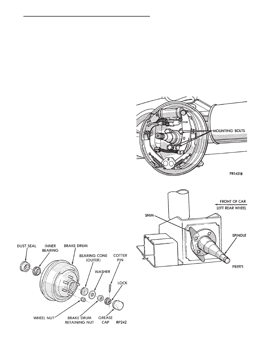
(8) Remove brake drum (Fig. 1).
(9) Loosen four (4) brake assembly and spindle
mounting bolts enough to allow clearance for shim
installation (Fig. 2). Do not remove mounting
bolts.
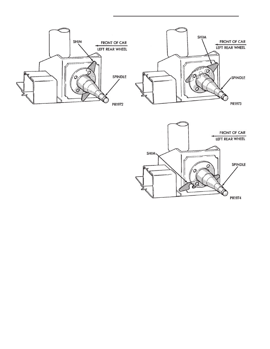
(10) Install shims as shown in Figs. 3, 4, 5 and 6
for desired wheel change. No more than two shims
on each spindle should be used to bring alignment
within acceptable range.
Wheel change by .3° per shim.
(11) Tighten down the 4 brake support plate and
spindle to axle mounting bolts until they are snug.
Then tighten the 4 bolts to the torque values listed
for the vehicle line which is being serviced.
• AA, AG, AJ, AP Bodies 75 NIm (55 ft. lbs.)
Fig. 2 Loosen Mounting Bolts
Fig. 3 Shim Installation for Toe-Out
Fig. 1 Remove Brake Drum
Ä
SUSPENSION AND DRIVESHAFTS
2 - 89
• AC, AY Bodies 108 NIm (80 ft. lbs.)
(12) Install brake drum (Fig. 1).
(13) Install washer and nut. Tighten adjusting nut
to 27-34 N
Im (240-300 in. lbs.) torque while rotating
wheel. Back off adjusting nut with wrench to com-
pletely release bearing preload. Finger tighten ad-
justing nut.
(14) Position nut lock with one pair of slots in-line
with cotter pin hole. Install cotter pin. The end play
should be 0.025-0.076 mm (0.001-0.003 inch). Clean
and install grease cap.
(15) Install wheel and tire assembly. Tighten
wheel nut to 129 N
Im (95 ft. lbs.) torque.
(16) Lower vehicle.
(17) Check alignment specifications.
Fig. 4 Shim Installation for Toe-In
Fig. 5 Shim Installation for Positive Camber
Fig. 6 Shim Installation for Negative Camber
2 - 90
SUSPENSION AND DRIVESHAFTS
Ä
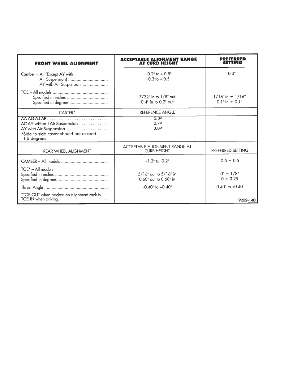
SPECIFICATIONS
ALIGNMENT SPECIFICATIONS AT CURB HEIGHT
Ä
SUSPENSION AND DRIVESHAFTS
2 - 91

REAR SUSPENSION TORQUE
SPECIFICATIONS
FRONT SUSPENSION TORQUE
SPECIFICATIONS
2 - 92
SUSPENSION AND DRIVESHAFTS
Ä
Нет комментариевНе стесняйтесь поделиться с нами вашим ценным мнением.
Текст