Chrysler Le Baron, Dodge Dynasty, Plymouth Acclaim. Manual — part 316
AUDIO SYSTEM
CONTENTS
page
page
ANTENNAS
. . . . . . . . . . . . . . . . . . . . . . . . . . . . 20
COMPACT DISC PLAYER
. . . . . . . . . . . . . . . . . 30
RADIOS
. . . . . . . . . . . . . . . . . . . . . . . . . . . . . . . . 1
SPEAKERS
. . . . . . . . . . . . . . . . . . . . . . . . . . . . 24
RADIOS
INDEX
page
page
Audio Diagnostic Test Procedures
. . . . . . . . . . . . . 1
Description
. . . . . . . . . . . . . . . . . . . . . . . . . . . . . . 1
Interference Elimination
. . . . . . . . . . . . . . . . . . . . . 1
Radio Removal AP Body Replacement
. . . . . . . . 19
Radio Removal—AA Body
. . . . . . . . . . . . . . . . . . 18
Radio Removal—AC and AY Bodies
. . . . . . . . . . 18
Radio Removal—AG and AJ Bodies
. . . . . . . . . . 18
DESCRIPTION
For operation of the factory installed standard and
optional radios and the optional compact disc player,
refer to the Sound Systems Operating Instructions
Manual supplied with the vehicle.
All vehicles are equipped with an Ignition-Off
Draw Connector which, is used when the vehicles are
originally shipped from the factory. This connector
which, is located near the battery, helps to prevent
battery discharge during storage. For specific connec-
tor type and location, refer to Group 8W, Wiring Di-
agrams.
This connector is included in the radio memory cir-
cuitry and should be checked if the memory of time
or radio station programming is inoperative.
INTERFERENCE ELIMINATION
Some components are used on vehicles equipped
with a radio capacitor, to suppress radio frequency
interference/static.
Capacitors are mounted in various locations, on the
generator either internal or external, internal to the
instrument cluster, and internal to the windshield
wiper motor.
Ground straps are mounted from radio chassis to
instrument panel support structure, engine to cowl,
across engine mount on right hand side. On vehicles
with air conditioning there is a strap from evapora-
tor valve to cowl. These ground straps should be se-
curely tightened to assure good metal to metal
contact. Ground straps conduct very small high fre-
quency electrical signals to ground and require clean
large surface area contact.
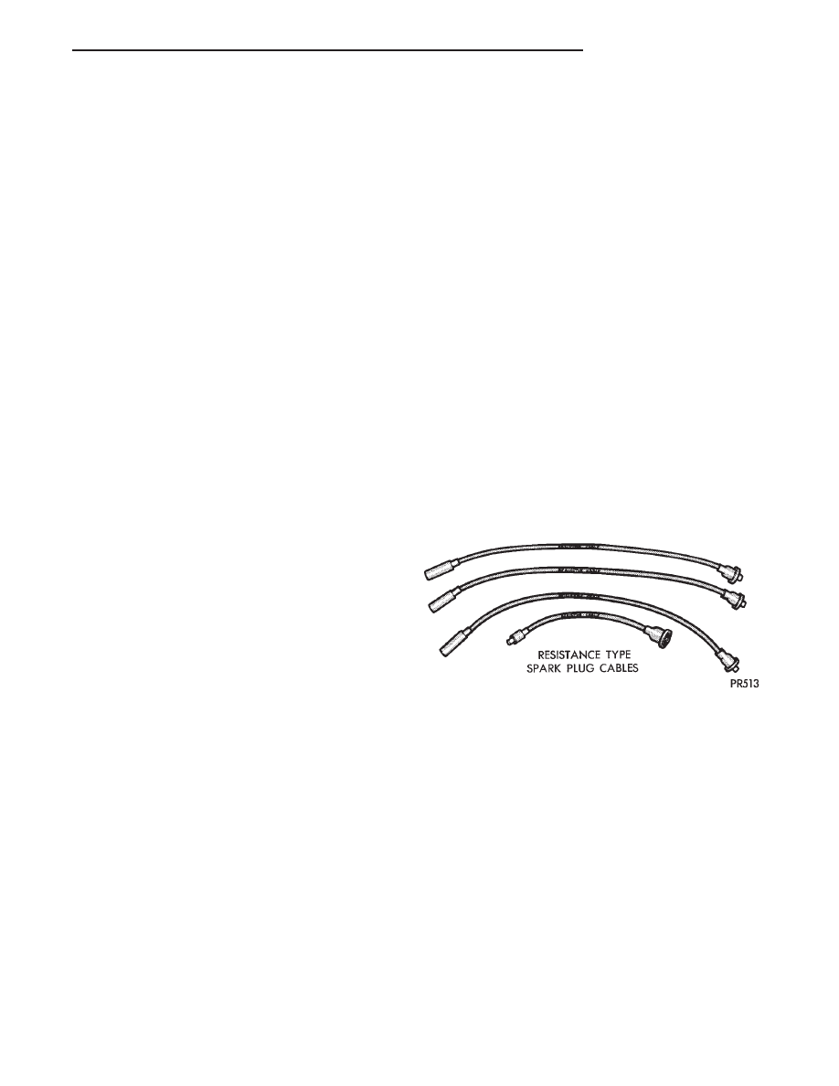
Radio resistance type spark plug cables in the high
tension circuit of the ignition system complete the in-
terference suppression (Fig. 1).
If radio noises are evident, be sure the capacitor
lead wires are making good contact on their respec-
tive terminals and are securely mounted. Faulty or
deteriorated spark plug wires should be replaced.
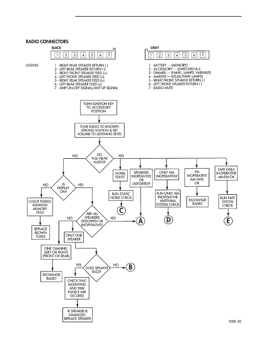
AUDIO DIAGNOSTIC TEST PROCEDURES
Whenever a audio malfunction occurs, first verify
that the radio wire harness is properly connected to
all connectors before starting normal diagnosis and
repair procedures. Refer to Audio Diagnostic Charts
and/or Radio Connector Circuit Chart (Fig. 2).
Fig. 1 Resistance Type Spark Plug Cables
Ä
AUDIO SYSTEM
8F - 1
AM/FM STEREO—CASSETTE TAPE
8F - 2
AUDIO SYSTEM
Ä
AM/FM STEREO—CASSETTE TAPE CONTINUED
Ä
AUDIO SYSTEM
8F - 3
AM/FM STEREO—CASSETTE TAPE CONTINUED
8F - 4
AUDIO SYSTEM
Ä
Нет комментариевНе стесняйтесь поделиться с нами вашим ценным мнением.
Текст