Chrysler Le Baron, Dodge Dynasty, Plymouth Acclaim. Manual — part 315
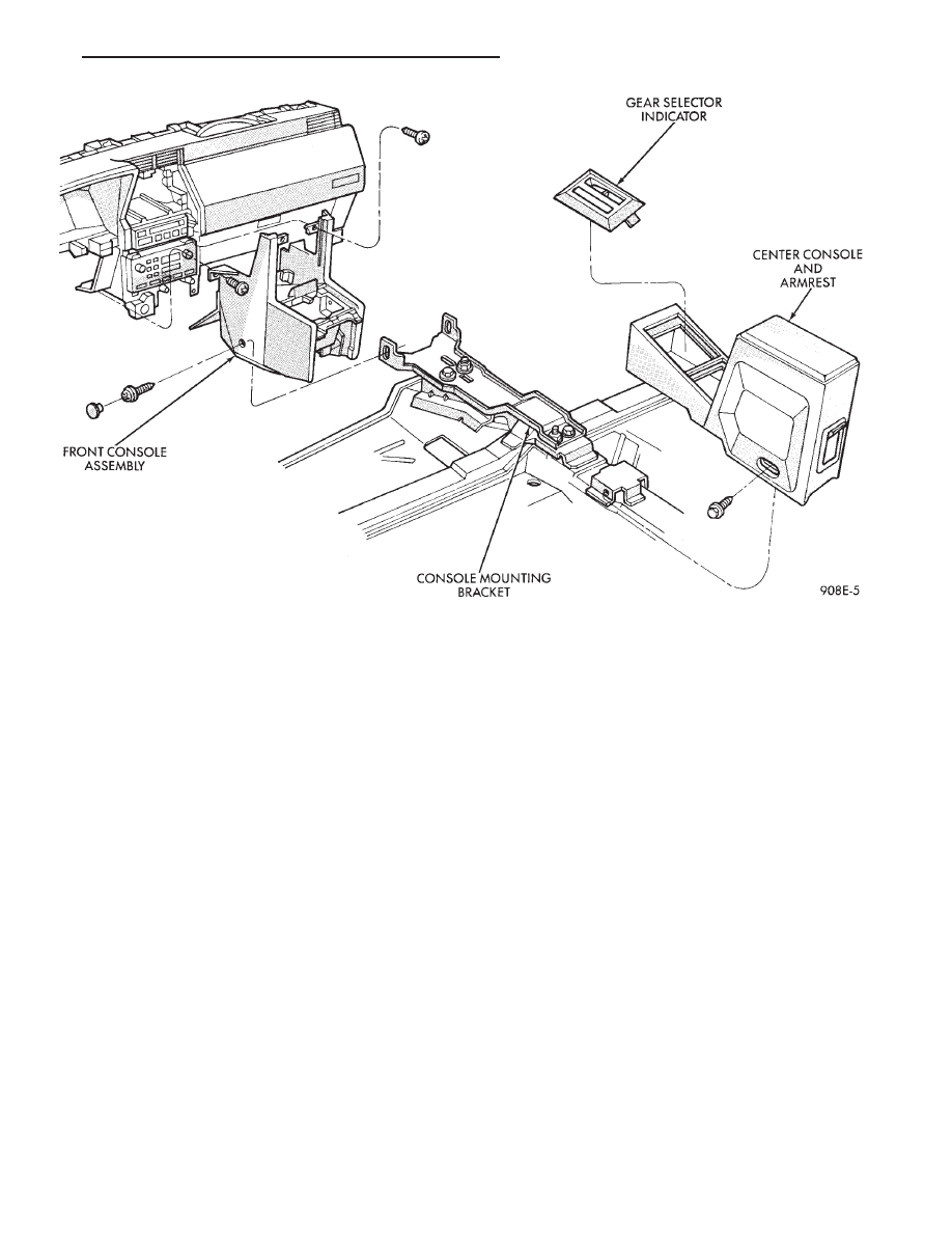
CENTER CONSOLE ASSEMBLY
REPLACEMENT
(1) Place transmission in neutral and remove
shifter handle.
(2) Unsnap transmission range indication bezel or
shift boot bezel from console, disconnect wiring and
remove bezel assembly (Fig. 27).
(3) Unsnap power window/mirror switch bezel,
when so equipped and disconnect switch wiring.
(4) Remove two screws from side of armrest.
(5) Remove arm rest and center console section as
a unit by lifting from the front and unsnapping from
front console section.
(6) For installation reverse above procedures. Ad-
just transmission range indicator in the PARK posi-
tion.
CONSOLE GEAR SELECTOR INDICATOR LAMP
REPLACEMENT
(1) Place shifter handle in Neutral position.
(2) Remove handle from shifter.
(3) Unsnap gear selector bezel and pull upward
(Fig. 27).
(4) Remove indicator lamp socket from bezel to re-
place lamp.
(5) For installation reverse above procedures. Ad-
just transmission range indicator in the PARK posi-
tion.
FRONT CONSOLE ASSEMBLY REPLACEMENT
(1) Remove shifter handle.
(2) Unsnap transmission range indicator bezel or
shift boot bezel from console assembly, disconnect
wiring and remove bezel assembly (Fig. 27).
(3) Unsnap power mirror/window switch bezel,
when so equipped and disconnect switch wiring.
(4) Open arm rest and remove three screws hold-
ing arm rest to center console retractor bracket.
(5) Remove armrest and center console section as a
unit by lifting and unsnapping from forward console
section.
(6) Remove center module bezel.
(7) Remove forward console and side walls as com-
plete unit by removing six sidewall attaching screws
to instrument panel and console bracket. Slide unit
rearward and lift to remove.
(8) For installation reverse above procedures.
(a) For adjustment move gearshift lever with
force into park position.
(b) Check gear selector indicator for proper
alignment.
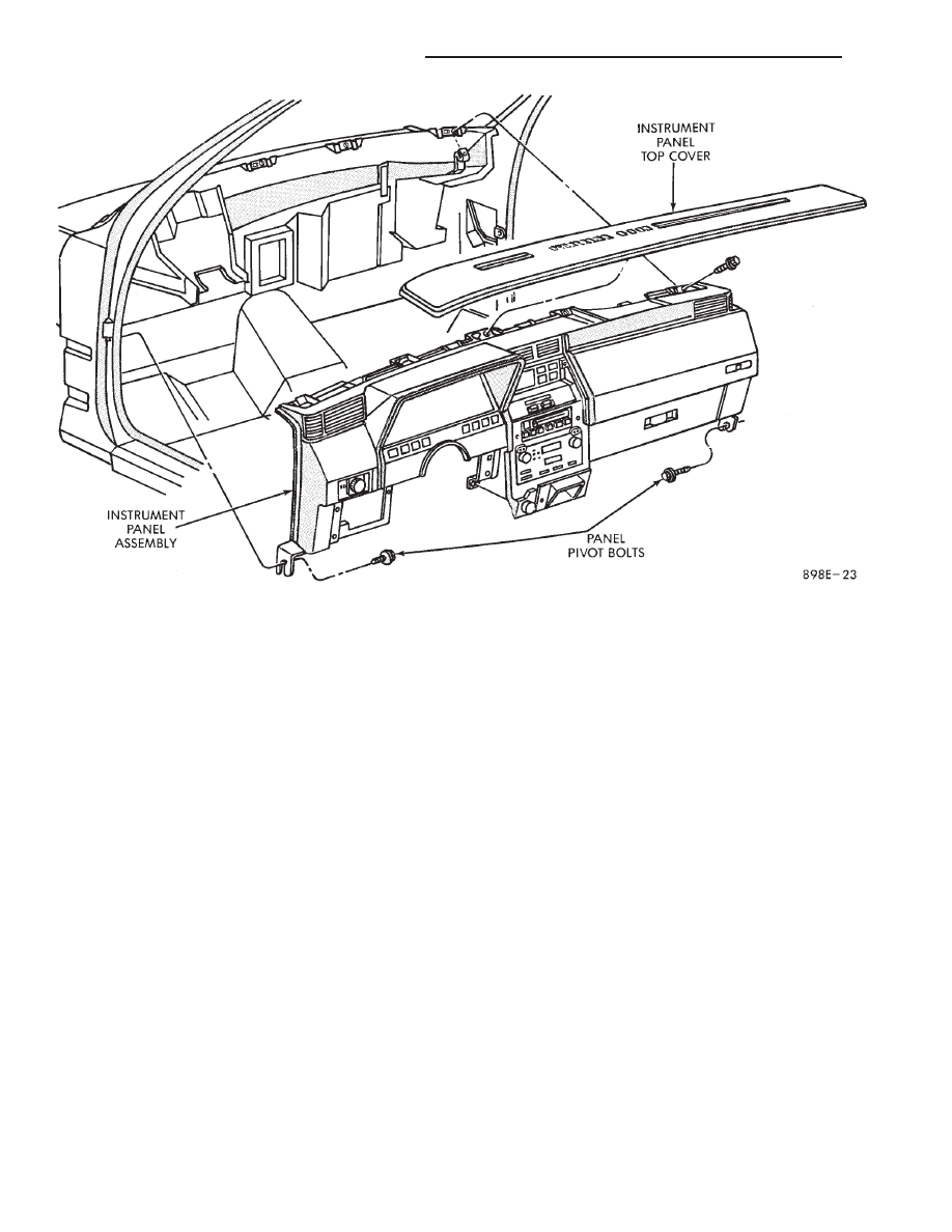
INSTRUMENT PANEL TOP COVER
REPLACEMENT
(1) Place trim-stick tool in groove between the
panel top cover and pad surface (FIG. 28).
Fig. 27 Front and Center Console with Transmission Range Indicator
Ä
INSTRUMENT PANEL AND GAUGES
8E - 71
(2) Pry cover up and forward until released from
instrument panel pad.
(3) Lift top cover upward and rearward to remove
from vehicle.
(4) For installation place top cover on panel open-
ing. Be certain that blades of top cover are located in
the retaining spring clips.
(5) Push forward and down to engage in pad.
INSTRUMENT PANEL REPLACEMENT
CAUTION: Disconnect negative battery cable, in en-
gine
compartment,
before
servicing
instrument
panel.
(1) Remove windshield wiper arms.
(2) Open hood and remove cowl top plastic cover.
(3) Remove windshield washer reservoir.
(4) Pull connector loose from the A/C resistor block
and push wiring and grommet through bulkhead into
passenger compartment.
(5) Remove the console/consolette assembly.
(6) Remove the passive restraint seat belt logic
control module wiring.
(7) Remove six attaching nuts securing the instru-
ment panel to console support brace.
(8) Remove the instrument panel to console sup-
port brace with the Air Bag System Diagnostic Mod-
ule attached.
(9) Remove right and left cowl side and scuff plate
trim moldings.
(10) Remove left and right A-pillar trim moldings.
(11) Remove instrument panel top cover (Fig. 28).
(12) Remove lower steering column cover.
(13) Disconnect the steering column wiring at the
25-way connector.
(14) Disconnect park brake, stop lamp and speed
control wiring.
(15) Remove five steering column support nuts and
lower steering column. Then remove two steering col-
umn attaching studs.
(16) Disconnect engine harness wiring at 18-way
and 16-way connectors located on the left side panel
support bracket.
(17) Remove glove box assembly.
(18) Remove the panel top cover assembly.
(19) Loosen the panel roll-down pivot bolts.
(20) Remove the defroster duct adapter from de-
froster duct.
(21) Remove screws which attach instrument panel
to windshield fence line. Roll panel down, attach
heavy wire to hold in position and remove defroster
duct retaining screws.
(22) Disconnect body wiring at the right side
18-way connector and left side 25-way connector.
(23) Disconnect temperature mode cable at in-line
connector. Disconnect resistor block and blower mo-
tor wiring connectors.
Fig. 28 Instrument Panel and Top Cover
8E - 72
INSTRUMENT PANEL AND GAUGES
Ä
(24) Disconnect antenna cable.
(25) Disconnect left and right demister hoses from
demister outlets on the panel.
(26) Remove instrument panel from vehicle.
(27) For installation reverse above procedures.
INTERIOR LAMP REPLACEMENT
The Dome Lamp operates when the doors are open
or headlamp switch is placed in courtesy position.
DOME LAMP
(1) Pry the forward or rearward edge of the dome
lamp to free it from the retaining bracket.
(2) Pry either the forward or rearward edge of the
lens away from the bezel and replace lamp.
(3) For installation, snap lens into bezel and then
bezel into bracket.
TRUNK LAMP
Pry along rearward portion of lens and pivot out of
trunk trim panel. Remove lens and replace lamp.
For installation, snap lens into trunk trim panel.
Ä
INSTRUMENT PANEL AND GAUGES
8E - 73
Нет комментариевНе стесняйтесь поделиться с нами вашим ценным мнением.
Текст