Chrysler Le Baron, Dodge Dynasty, Plymouth Acclaim. Manual — part 359
• If not remove mirror glass and test the wires for
continuity. If no continuity repair wires.
• If wires are OK, replace mirror glass.
• To test defogger switch refer to Group 8N, Rear
Window Defogger, Control Switch/Timer Relay Mod-
ule Test.
MIRROR SWITCH REPLACEMENT—AA BODY
(1) Remove door trim panel.
(2) Remove set screw from pillar trim bezel.
(3) Remove pillar trim bezel retaining screws.
(4) Disconnect switch wiring (Fig. 9).
(5) Remove switch from switch bezel.
(6) For installation, reverse above procedure.
MIRROR SWITCH REPLACEMENT—AG AND AJ
BODIES
(1) Carefully pry switch from switch bezel (Fig.
10).
(2) Remove switch wiring connector.
(3) For installation, reverse above procedure.
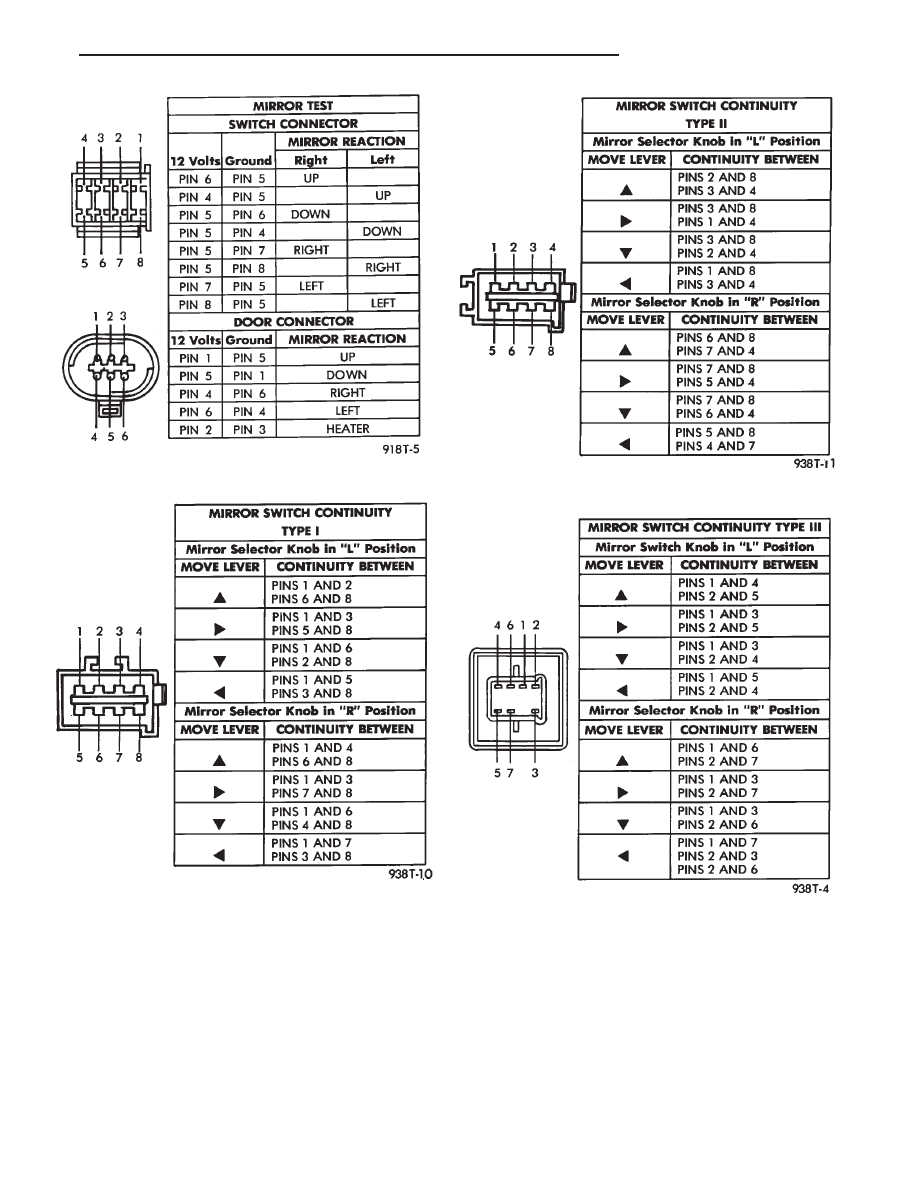
Fig. 5 MIRROR TEST—AG and AJ Bodies
Fig. 6 Type I Mirror Switch Test
Fig. 7 Type II Mirror Switch Test
Fig. 8 Type III Mirror Switch Test
Ä
POWER MIRRORS
8T - 3
MIRROR SWITCH REPLACEMENT—AP BODY
(1) Remove power mirror switch bezel from mount-
ing position (Fig. 11).
(2) Turn bezel over and remove two switch retain-
ing screws.
(3) Disconnect wiring at switch connector.
(4) Remove switch from vehicle.
(5) For installation, reverse above procedure.
MIRROR SWITCH REPLACEMENT—AC AND AY
BODIES
(1) Remove door trim panel.
(2) Remove three pillar trim bezel retaining screws
and pull bezel from door.
(3) Loosen remote control switch retaining screw
and pull switch from bezel.
(4) Disconnect switch wiring at connector near bot-
tom of door and pull switch and harness from door
(Fig. 12).
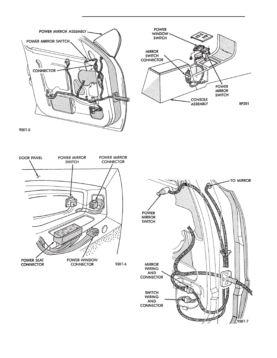
Fig. 9 Power Mirror Switch—AA Body
Fig. 10 Power Mirror Switch—AG, and AJ Bodies
Fig. 11 Power Mirror Switch—AP Body
Fig. 12 Power Mirror Switch and Wiring—AC and AY
Bodies
8T - 4
POWER MIRRORS
Ä
(5) For installation, reverse above procedure.
MIRROR ASSEMBLY REPLACEMENT—AA BODY
(1) Remove door trim panel.
(2) Remove switch set screw from door pillar trim.
(3) Remove two pillar trim bezel screws and re-
move bezel (Fig.13).
(4) Disconnect mirror wiring connector.
(5) Remove three mirror retaining nuts and pull
mirror and harness from door.
(6) For installation, reverse above procedure. Test
operation of mirror before installing door trim panel.
MIRROR ASSEMBLY REPLACEMENT—AG BODY
(1) Remove door trim panel.
(2) Disconnect mirror wiring at connector (Figs. 14
and 15).
(3) Remove plugs used to conceal mirror mounting
nuts.
(4) Remove mirror mounting nuts and release mir-
ror from door.
(5) For installation, reverse above procedure. Test
mirror for proper operation before installing door
trim panel.
MIRROR ASSEMBLY REPLACEMENT—AJ BODY
(1) Remove door trim panel.
(2) Remove door speaker and disconnect mirror
wiring connectors (Fig. 16).
(3) Remove plugs used to conceal mirror mounting
nuts.
(4) Remove mirror mounting nuts and release mir-
ror from door.
(5) For installation, reverse above procedure. Test
mirror for proper operation before installing door
trim panel.
MIRROR ASSEMBLY REPLACEMENT—AP BODY
(1) Remove door trim panel.
(2) Disconnect wiring at connector (Figs. 17 and
18).
(3) Remove door bezel and small plug to gain ac-
cess to mirror retaining nuts.
(4) Remove three mirror retaining nuts and re-
move mirror from vehicle.
(5) For installation, reverse above procedure. Test
mirror for proper operation before installing door
trim panel.
MIRROR ASSEMBLY REPLACEMENT—AC AND AY
BODIES
(1) Remove door trim panel.
(2) Remove three pillar trim bezel retaining screws
and pull bezel from door.
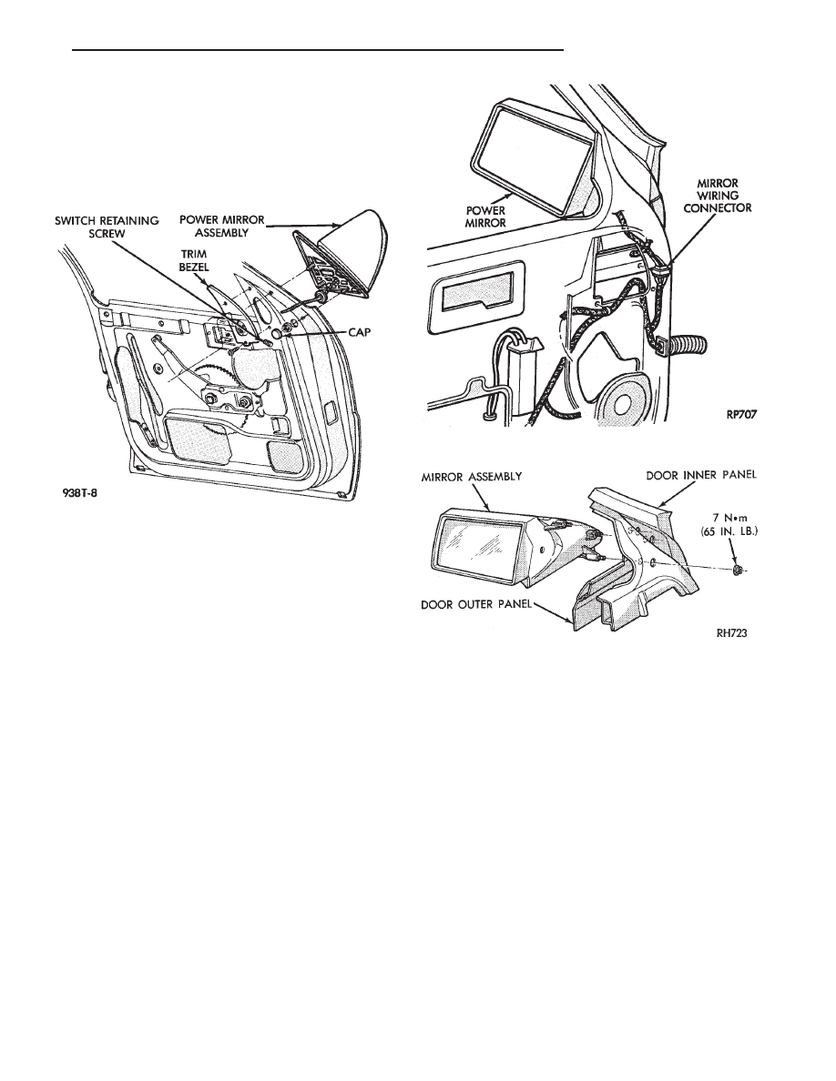
Fig. 13 Power Mirror Assembly—AA Body
Fig. 14 Power Mirror Wiring—AG Body
Fig. 15 Power Mirror Assembly—AG Body
Ä
POWER MIRRORS
8T - 5

(3) Disconnect mirror wiring connector near bot-
tom of door (Fig. 19).
(4) Remove two mirror retaining nuts and screw
one, and pull mirror and harness from door.
(5) For installation, reverse above procedure. Test
mirror for proper operation before installing door
trim panel.
INSIDE MIRROR/READING LAMPS REPLACEMENT
(1) Release locking tab on front side of mirror stay
by pushing down. While holding tab down, pull mir-
ror rearward to remove (Fig. 20).
(2) Remove visor center attaching clips.
(3) Remove header end caps.
(4) Remove header trim.
(5) Disconnect wiring connector.
(6) For installation, reverse above procedure. En-
sure the mirror is fully locked into place.
INSIDE MIRROR/READING LAMPS BULB/LENS
REPLACEMENT
(1) Place a small thin blade tool in the notch at
the outside end of the lens housing and pry off the
lens housing.
(2) Remove lamp socket from lens housing. Re-
move bulb from socket and replace if necessary.
(3) Remove lens by applying pressure on locking
tabs to remove lens.
(4) Replacing lens, set into place apply pressure
until it is locked into position.
(5) For installation, reverse above procedure.
Fig. 16 Power Mirror Assembly—AJ Body
Fig. 17 Power Mirror Wiring—AP Body
Fig. 18 Power Mirror Assembly—AP Body
Fig. 19 Power Mirror Assembly—AC and AY Body
8T - 6
POWER MIRRORS
Ä
Нет комментариевНе стесняйтесь поделиться с нами вашим ценным мнением.
Текст