Chrysler Le Baron, Dodge Dynasty, Plymouth Acclaim. Manual — part 360
AUTOMATIC DAY/NIGHT INSIDE MIRROR
Operational test:
• Turn ignition switch to the ON position with the
vehicle in park (Fig. 21).
• Place mirror switch in the high position.
• Cover the forward facing sensor with dark cloth to
keep out any ambient light.
• Shine a light into the rear facing sensor, watch to
see if the mirror darkens.
With the mirror darkened, place the vehicle in re-
verse, the mirror should return to its normal condi-
tion.
If the above conditions are met the mirror is oper-
ating properly.
• If not test voltage.
Test three way connector harness. Refer to Fig. 21.
(1) Pin 1 Ignition Switch in run position, should
have battery voltage.
(2) Pin 2 Should have continuity to Ground.
(3) Pin 3 When the transmission is in reverse,
should have battery voltage.
(4) If test is OK replace Mirror.
(5) If not refer, to Wiring Diagrams manual to test
the circuits.
AUTOMATIC DAY/NIGHT INSIDE MIRROR WITH
ULTRALIGHT HEADLAMP CONTROL
CAUTION:When JUMP STARTING the vehicle, be-
fore cranking engine turn ignition ON and turn OFF
the Automatic Headlamp Control.
The mirror automatically reduces the amount of
headlamp glare from rear approaching traffic and
provides automatic headlamp control (Fig. 22).
SELF DIAGNOSTIC MODE—OPERATIONAL
TEST:
(1) Place shift selector in park (P) or Neutral (N)
position. With ignition OFF, press and hold AUTO
MIRROR and AUTO LAMP (headlamp) buttons, turn
ignition switch ON. When LED indicators start
flashing, release buttons.
(a) The button LED indicators should flash for
about five seconds.
• AUTO MIRROR
• DARK
• AUTO LAMP
(b) If they continue to flash much longer than
five seconds, the mirror assembly is defective.
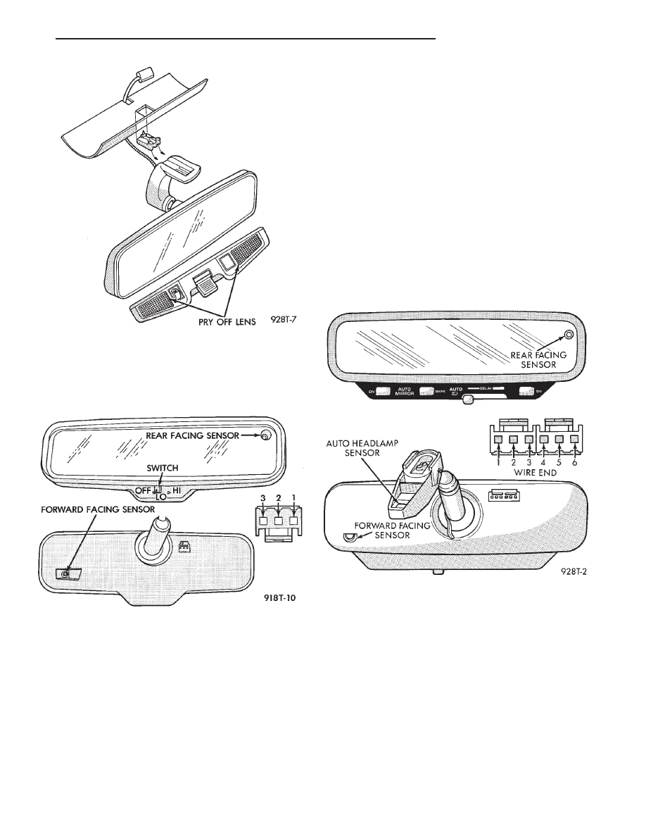
Fig. 20 Header Mirror/Reading Lamps
Fig. 21 Automatic Day / Night Mirror
Fig. 22 Automatic Day / Night Mirror with Ultralight
Headlamp Control
Ä
POWER MIRRORS
8T - 7
(2) The headlamps and parking lamps should turn
ON for about five seconds.
• AUTO MIRROR LED
• DARK LED
• AUTO LAMP LED
• The LED indicators blink for about 5 seconds.
• If the three indicators continue to blink consider-
ably longer than 5 seconds, then the mirror assembly
is defective.
(3) The mirror should change to dim state.
(a) Place shift selector in reverse (R), with igni-
tion switch ON:
• AUTO MIRROR LED indicator ON
• DARK LED indicator flashing
• Lasting about 15 seconds
(b) The mirror should slowly change to bright
state.
(c) If the ignition is not turned OFF within the
15 second time period, the mirror will reset to its
previous setting.
The previous conditions are OK, the mirror is op-
erating properly.
If not OK, continue with voltage tests below.
VOLTAGE TEST
To test for voltage insert voltmeter probe into wire
end of connector to contact terminal.
Pin 1 ignition voltage
(a) Ignition switch OFF, zero volts.
(b) Ignition switch ON, battery voltage.
Pin 2 battery voltage
(a) Battery voltage at all times.
(b) No voltage, check 15 amp. fuse.
Pin 3 Ground
(a) Continuity to ground.
(b) No voltage
Pin 4 Reverse over-ride
(a) Ignition OFF, zero voltage.
(b) Ignition ON shift selector in Reverse (R), bat-
tery voltage.
(c) Ignition ON shift selector in any position
other than Reverse (R), zero voltage.
Pin 5 Headlamp relay
(a) Battery voltage at all times from headlamp
relay.
(b) No battery voltage, test headlamp relay.
Pin 6 Park lamp relay
(a) Ignition switch ON, battery voltage feed from
park lamp relay.
(b) Ignition switch OFF, zero voltage.
(c) Ignition ON, No battery voltage test park
lamp relay.
If Voltage Test are OK, replace mirror assembly.
If not OK, refer to Wiring Diagrams manual.
8T - 8
POWER MIRRORS
Ä
CHIME WARNING/REMINDER SYSTEM
CONTENTS
page
page
BODY CONTROLLER REPLACEMENT
. . . . . . . . 5
CHIME MODULE REPLACEMENT AA and AP
BODIES
. . . . . . . . . . . . . . . . . . . . . . . . . . . . . . 5
CHIME SYSTEM DIAGNOSIS—AA AND AP
BODIES
. . . . . . . . . . . . . . . . . . . . . . . . . . . . . . 2
CHIME SYSTEM DIAGNOSIS—AC, AG, AJ
AND AY BODIES
. . . . . . . . . . . . . . . . . . . . . . . 3
CHIME WARNING/REMINDER SYSTEM TEST
. 1
GENERAL INFORMATION . . . . . . . . . . . . . . . . . . 1
HEADLAMP SWITCH REPLACEMENT
. . . . . . . . 5
KEY-IN SWITCH REPLACEMENT
. . . . . . . . . . . . 5
SEAT BELT BUCKLE REPLACEMENT
. . . . . . . . 5
SEAT BELT BUCKLE SWITCH TEST BUZZER
SYSTEM
. . . . . . . . . . . . . . . . . . . . . . . . . . . . . . 1
SERVICE PROCEDURES
. . . . . . . . . . . . . . . . . . . 5
TIMED BUZZER-RELAY TEST—AP BODY . . . . . 1
GENERAL INFORMATION
WARNING: ON VEHICLES EQUIPPED WITH AN AIR
BAG REFER TO THE AIR BAG PORTION OF THIS
SECTION FOR STEERING WHEEL OR SWITCH RE-
MOVAL AND INSTALLATION PROCEDURES.
BUZZER SYSTEM
The seat belt warning system uses both visual and
audible signals. A combined seat belt and key warn-
ing buzzer with a red light on the instrument panel.
The system will always illuminate the seat belt
warning lamp for four to eight seconds when the ig-
nition switch is turned to the ON position. Also, only
if the driver does not fasten his seat belt, the buzzer
will sound during the same time interval. Passenger
belts are not connected to the system.
A timed buzzer-relay is used to operate the system
for the time period. It consists of a time delay mech-
anism and buzzer assembly. Only the driver’s seat
belt buckle has a switch that is connected to the sys-
tem.
CHIME WARNING/REMINDER SYSTEM
The chime warning/reminder system is similar in
operation to the buzzer system except for a more
pleasant sounding tone. This chime type tone sounds
for all three warning/reminder conditions; namely
headlamps left on, keys left in ignition and fasten
seat belt.
TIMED BUZZER-RELAY TEST—AP BODY
PREPARATION
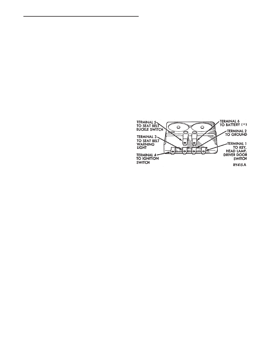
(1) Remove timed buzzer-relay (Fig. 1).
(2) Connect one end of a jumper wire to a 12 volt
supply.
(3) Connect a test lamp equipped with a number
194 lamp or equivalent, between terminal number 3
of relay and ground.
(4) Ground terminals 2 and 5 of relay.
TEST
(1) Connect 12 volt jumper wire to terminal num-
ber 4 of timed buzzer-relay, look at test lamp and lis-
ten for buzzer.
(2) Test lamp should come on and buzzer should
sound for four to eight seconds and then both should
go off; if not, replace timed buzzer-relay.
(3) If operation is okay, check all wiring in vehicle
for opens, shorts, or poor connections.
SEAT BELT BUCKLE SWITCH TEST BUZZER
SYSTEM
Test timed buzzer-relay. If it checks OK, check the
wiring between seat belt buckle and ground. The
wire that goes to terminal 5 of relay from buckle
switch, refer to Fig. 2 and 3. If they check out okay,
replace buckle switch.
CHIME WARNING/REMINDER SYSTEM TEST
FASTEN SEAT BELTS
To test the fasten seat belts function, turn the ig-
nition switch to the ON position with the driver’s
seat belt unbuckled. The seat belt warning lamp
should light for four to eight seconds and the tone
should sound three to five times.
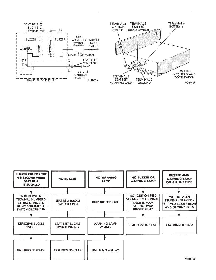
Fig. 1 Timed Buzzer-Relay Terminal Identification
Ä
CHIME WARNING/REMINDER SYSTEM
8U - 1
HEADLAMPS LEFT ON
To test the headlamps left on function, turn head-
lamps on with drivers door open. Chime should
sound until headlamps are turned off or drivers door
is closed.
KEY LEFT IN IGNITION
To test the key left in ignition function, insert key
into the ignition and open drivers door. Chime
should sound until key is removed from ignition or
drivers door is closed.
CHIME SYSTEM DIAGNOSIS—AA AND AP BODIES
WARNING: ON VEHICLES EQUIPPED WITH AN AIR
BAG REFER TO THE AIR BAG PORTION OF THIS
SECTION FOR STEERING WHEEL OR SWITCH RE-
MOVAL AND INSTALLATION PROCEDURES.
CONDITION: NO TONE WHEN IGNITION
SWITCH IS TURNED ON AND DRIVERS SEAT
BELT OR AUTOMATIC SHOULDER HARNESS
IS UNBUCKLED
PROCEDURE
(1) Check seat belt buckle switch (drivers seat) or
rotary switch in automatic shoulder harness retrac-
tor for a ground when unbuckled.
(2) Check for battery feed at terminal 6 and igni-
tion feed at terminal 4 of chime module (Fig. 4 and
5).
Fig. 3 Seat Belt Warning System Diagnosis
Fig. 4 Chime Module Terminal Identification
Fig. 2 Buzzer System Wiring Schematic
8U - 2
CHIME WARNING/REMINDER SYSTEM
Ä
Нет комментариевНе стесняйтесь поделиться с нами вашим ценным мнением.
Текст