Chrysler Le Baron, Dodge Dynasty, Plymouth Acclaim. Manual — part 180
INSTALLATION
Reverse the preceding operation.
REAR SEAT BELT RETRACTOR
REMOVAL (FIG. 32)
(1) Remove quarter trim panel as necessary to
gain access to the rear seat belt retractor.
(2) Remove snap-on cover from shoulder harness
turning loop.
(3) Remove bolt holding turning loop to rear seat
back support reinforcement.
(4) Remove bolt holding retractor to rear seat back
support reinforcement.
(5) Separate retractor from vehicle.
INSTALLATION
Reverse the preceding operation.
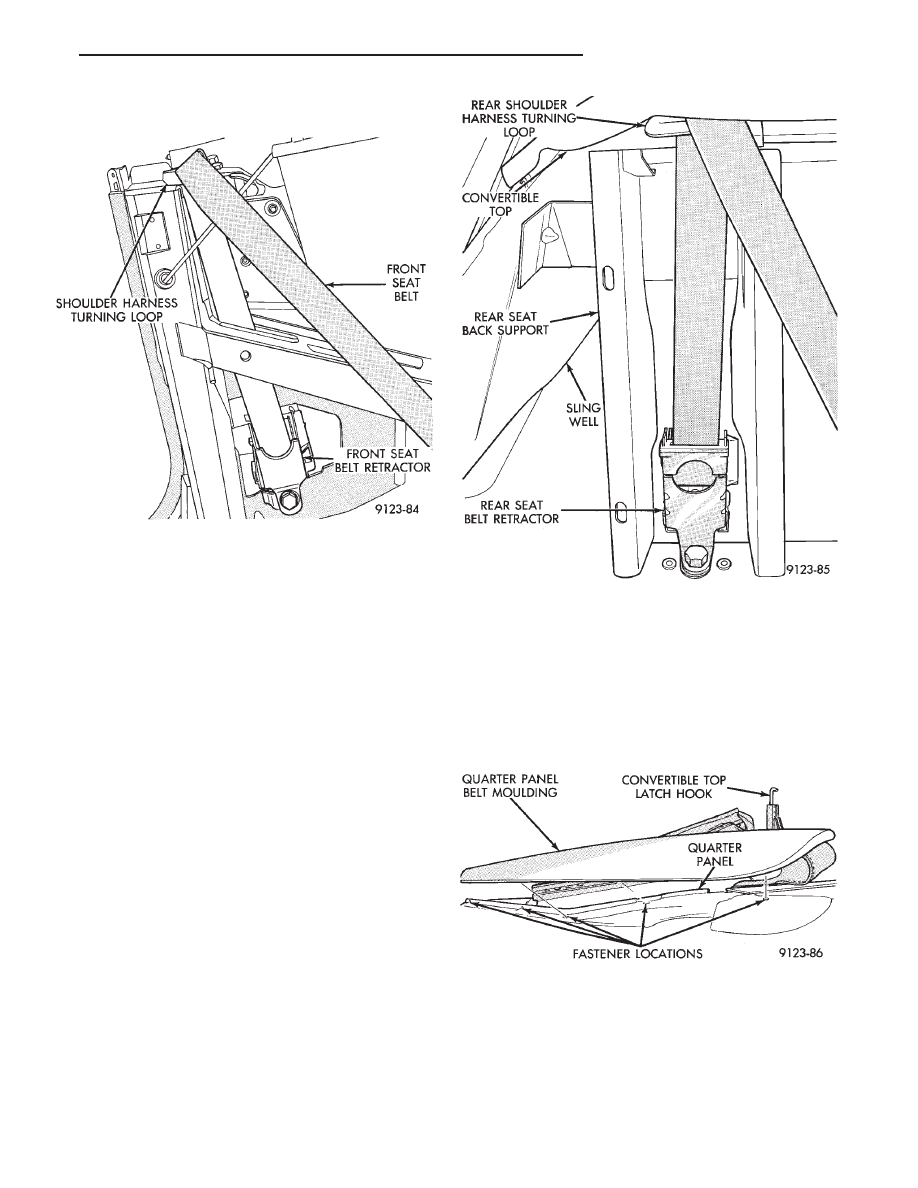
QUARTER PANEL BELT MOULDING
REMOVAL (FIG. 33)
(1) Lower convertible top.
(2) Remove quarter trim panel as necessary to
gain access to the belt moulding and weatherstrip at-
taching screws through the opening at the top of the
quarter panel.
(3) Remove screws holding moulding to inner quar-
ter panel in quarter glass opening.
(4) Remove nuts holding moulding to quarter
panel along top opening.
(5) Raise trunk lid. Remove nut holding moulding
to quarter panel from behind quarter panel reinforce-
ment.
(6) Separate quarter panel belt moulding from ve-
hicle.
INSTALLATION
Apply sealing putty around mounting studs on
back of moulding and reverse the removal operation.
TRUNK LID LINING
REMOVAL (FIG. 34)
(1) Raise trunk lid.
(2) Remove screws holding trunk lid lining to in-
side of trunk lid.
(3) Support trunk lid in the full up position.
(4) Disconnect trunk lid prop cylinders.
(5) Separate trunk lid lining from vehicle.
Fig. 31 Front Seat Belt Retractor
Fig. 32 Rear Seat Belt Retractor
Fig. 33 Quarter Panel Belt Moulding
Ä
AP/27 CONVERTIBLE
23 - 129

INSTALLATION
Reverse the preceding operation.
TRUNK LID APPLIQUE
REMOVAL (FIG. 35)
(1) Remove trunk lid lining as necessary to gain
access to applique attaching nuts.
(2) Remove nuts holding applique to trunk lid.
(3) Separate applique from trunk lid.
(4) Disconnect center high mounted stop lamp wire
connector.
(5) Remove applique from vehicle.
INSTALLATION
Apply sealing putty around mounting studs on
back of applique and reverse the removal operation.
TRUNK OPENING WEATHERSTRIP
REMOVAL (FIG. 36)
(1) Raise trunk lid.
(2) Pull trunk lid opening weatherstrip from pinch
flange around opening.
(3) Separate weatherstrip from vehicle.
INSTALLATION
Position weatherstrip at center of rearward pinch
flange. Push weatherstrip onto pinch flange around
trunk opening and join the ends of the weatherstrip
when they meet.
TRUNK LID
REMOVAL (FIG. 37)
(1) Raise trunk lid to full up position.
(2) Disconnect the trunk lamp wire connector, if
equipped.
(3) Mark all bolt and hinge attachment locations
with a grease pencil to provide reference marks for
installation. When installing trunk lid, align all
marks and secure bolts. The trunk lid should be
aligned to 4 mm (0.160 in.) gap to the quarter panels
and flush across the top surfaces along quarter pan-
els.
(4) Support trunk lid and remove prop-rod cylin-
ders.
(5) Remove the top trunk lid to hinge attaching
bolts and loosen the bottom bolts until they can be
removed by hand.
(6) With assistance of a helper at the opposite side
of the vehicle, remove the remaining bolts. Separate
the trunk lid from the vehicle.
INSTALLATION
Reverse the preceding operation.
TRUNK HINGE LID
REMOVAL (FIG. 38)
(1) Raise and support trunk lid in the full up posi-
tion.
(2) Remove pivot bolts holding trunk lid hinge to
trunk opening side panel.
Fig. 34 Trunk Lid Lining and Prop Cylinder
Fig. 35 Trunk Lid Applique
Fig. 36 Trunk Opening Weatherstrip
23 - 130
AP/27 CONVERTIBLE
Ä

(3) Mark all bolt and hinge attachment locations
with a grease pencil to provide reference marks for
installation. When installing hinge, align all marks
and secure bolts. The trunk lid should be aligned to 4
mm (.160 in.) gap to the quarter panels and flush
across the top surfaces along quarters.
(4) Remove bolts holding hinge to trunk lid and
separate hinge from vehicle.
INSTALLATION
Reverse the preceding operation.
CONVERTIBLE TOP ADJUSTMENTS
When a convertible top component is aligned to
proper fit and finish specifications, weatherstrips and
seals will not always make proper contact. In these
cases, the use of shims, spacers, caulking putty and
foam adhesive backed tape will be required to gain
proper seal compression. Align weatherstrip and seal
channels or retainers so the contact surfaces are
smooth and make full contact with mating surfaces.
A paper strip, equal in size to a dollar bill, should be
able to be drawn through the contact surfaces with-
out tearing the paper. A reasonable amount of effort
should be required to pull the paper through.
Bolt on body panels should be aligned to the weld
on body components. The door should be aligned to
the quarter panel, rocker panel and A-pillar. The
gaps between panels should be as equal as possible.
When the door is fitted properly, the door glass can
be aligned to roof rail and A-pillar weatherstrips. Af-
ter verifying the door and door glass alignment, the
quarter glass can be aligned to the door glass and
rear roof rail.
DOOR GLASS ALIGNMENT
GLASS UP-STOP
The door glass up-stop bumper can be adjusted to
raise or lower the glass in the full up position.
(1) Remove door trim panel and water shield.
(2) Loosen up-stop bolt.
(3) Adjust bracket.
(4) Tighten up-stop bolt.
DIVISION BAR ALIGNMENT
The rear of the glass can be aligned up or down by
shifting the bottom attachment of the division bar.
Division bar adjustments are small and may not be
possible on some vehicles.
(1) Remove door trim panel and water shield.
(2) Loosen blot holding bottom of division bar to
inner door panel.
(3) Loosen bolt holding division bar to door inner
panel below stationary glass.
(4) Shift division bar forward or rearward to
achieve proper adjustment.
(5) Tighten bolts.
CONVERTIBLE TOP LATCH HOOKS
(1) Disengage top latches and raise top halfway.
(2) Loosen set screw locking latch hook in position.
(2) Rotate latch hook in or out to adjust latching
effort and roof header weatherstrip compression.
(3) Verify latching effort and tighten set screws.
ROOF RAIL WEATHERSTRIP RETAINER
(1) Disengage top latches and raise top halfway.
(2) Verify that door glass is all the way up and
properly aligned.
Fig. 37 Trunk Lid
Fig. 38 Trunk Lid Hinge
Ä
AP/27 CONVERTIBLE
23 - 131
(3) Loosen nuts holding roof rail weatherstrip re-
tainer to roof rail. Shift retainer inboard or outboard
to achieve proper alignment.
(4) Tighten nuts to hold retainer to roof rail and
latch top header.
(5) Verify weatherstrip sealing and door closing ef-
fort.
QUARTER GLASS AND ROLLER BRACKET
QUARTER GLASS
(1) Verify that door glass is properly aligned.
(2) Loosen nut holding top of quarter glass to rear
roof rail.
(3) Shift quarter glass inboard or outboard, for-
ward or rearward to achieve proper alignment.
(4) Tighten nut to hold top of quarter glass to rear
roof rail.
(5) Verify door glass operation and weatherstrip
sealing.
ROLLER BRACKET
The roller bracket controls the in and out move-
ment at the bottom for the quarter glass.
(1) Remove quarter trim panel as necessary to
gain access to the bottom of the quarter glass.
(2) Lower convertible top.
(3) Loosen bolts holding roller bracket to quarter
panel reinforcement.
(4) Align roller bracket to reduce quarter belt
weatherstrip contact when top is raised and proper
sash weatherstrip compression against the door
glass.
(5) Tighten bolts to hold roller to quarter panel
and verify top operation and weatherstrip sealing.
TOP STACK DOWN-STOP
Adjust down-stop in or out to set top stack down
position height.
CAUTION: Avoid setting top stack position too low,
top cover can be pinched and cut between wheel-
house and fourth bow.
Seal base of down-stop with silicone after adjust-
ing to prevent water leaks.
TOP STACK UP-STOP
Adjust up-stop in or out to change the contact with
the rear rail. This will effect the fore/aft position of
the No. 1 bow.
FOURTH ROOF BOW SLAT
Adjust the fourth roof bow slat to reduce wrinkles
and bagging around rear window and sail panels.
(1) Verify convertible top is up and latched.
(2) Loosen bolts holding the slat to the fourth roof
bow.
(3) Slide the bow up or down as necessary and
tighten bolts.
REAR TENSIONER PLATE
Adjust rear tensioner plate by loosening screws, po-
sitioning plate forward or backward, and tightening
screws. Tension can be adjusted on the back of the
top cover by varying contact.
23 - 132
AP/27 CONVERTIBLE
Ä
Нет комментариевНе стесняйтесь поделиться с нами вашим ценным мнением.
Текст