Chrysler Le Baron, Dodge Dynasty, Plymouth Acclaim. Manual — part 204
(5) Check resistance across pins #4 and #5 of the
21-way connector for a shorted actuator motor. Resis-
tance should be between 20 and 50 ohms. If not cor-
rect, replace actuator.
DIAGNOSTIC TROUBLE CODE 4—ACTUATOR
DRIVE COMMON SIGNAL NOT HIGH
If both Diagnostic Trouble Codes 4 and 5 oc-
cur simultaneously, do both procedures. There
is typically only 1 failure.
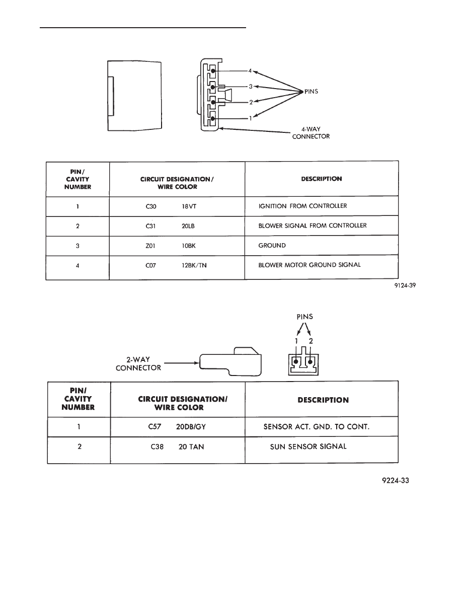
Fig. 3 Pin outs for 4-Way Connector
Fig. 4 Pin outs for Sun Sensor 2-Way Connector
Ä
HEATING AND AIR CONDITIONING
24 - 77
(1) Disconnect terminal #4 on the ATC control 21-
way connector and retest the system. Removing this
terminal may generate additional Diagnostic Trouble
Codes. Disregard these at this time.
(2) If Diagnostic Trouble Code 4 reappears, replace
control.
(3) If code 4 does not reappear, the problem is a
shorted actuator motor or a short to ground in circuit
#34 (pin #4).
(4) Remove 21-way connector and check for conti-
nuity from pin #4 to chassis ground. There should
not be any continuity. If continuity is there, repair
wiring and retest.
(5) Check resistance across pins #4 and #5, #4
and #6, and #4 and #15 of the 21-way connector for
a shorted actuator motor. Resistance should be be-
tween 20 and 50 ohms. If not correct, replace actua-
tor involved.
DIAGNOSTIC TROUBLE CODE 5—FRESH/
RECIRC ACTUATOR DRIVE SIGNAL NOT HIGH
If both Diagnostic Trouble Codes 4 and 5 oc-
cur simultaneously, do both procedures. There
is typically only 1 failure.
(1) Disconnect terminal #15 on the ATC control
21-way connector and retest the system. Removing
this terminal may generate additional Diagnostic
Trouble Codes. Disregard these at this time.
(2) If Diagnostic Trouble Code 5 reappears, replace
control.
(3) If code 5 does not reappear, the problem is a
shorted fresh/recirc door actuator motor. It could also
be a short to ground in circuit #32 (pin #15).
(4) Remove 21-way connector and check for conti-
nuity from pin #15 to chassis ground. There should
not be any continuity. If continuity is there, repair
wiring and retest.
(5) Check resistance across pins #15 and #4 of the
21-way connector for a shorted actuator motor. Resis-
tance should be between 20 and 50 ohms. If not cor-
rect, replace actuator.
DIAGNOSTIC TROUBLE CODE
6—COMPRESSOR DRIVE SIGNAL NOT HIGH
(1) Disconnect the low pressure cut out switch and
retest diagnostics.
(2) If code 6 does not reappear, then the problem is
in the A/C signal circuit C02. Check for wiring prob-
lem between the low pressure cut out switch and the
engine controller, or a bad engine controller.
(3) If code 6 does reappear, remove the 21-way con-
nector from the control and check for a short between
pin #13 and chassis ground. This test will check the
wire from the control to the low pressure cut out
switch for a short to ground.
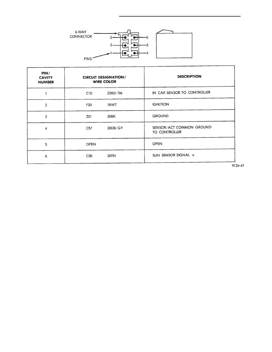
Fig. 5 Pin outs for 6-Way Connector In-Car Sensor and Sun Sensor
24 - 78
HEATING AND AIR CONDITIONING
Ä

Fig. 6 ATC Circuits
Ä
HEATING AND AIR CONDITIONING
24 - 79
(4) If pin #13 shows continuity, repair circuit C02
and retest.
(5) If no continuity is shown, replace the ATC con-
trol and retest.
DIAGNOSTIC TROUBLE CODE 7—BLOWER
DRIVE SIGNAL NOT HIGH
First check the 4-way connector to the power
module for correct installation
(1) With the ignition ON, check for ignition volt-
age to the power module pin #1 from the ATC con-
trol. If ignition is present at the power module,
proceed to step 3. If not proceed to step 2.
(2) With the 21-way connector still connected and
the ignition ON, check for power module ignition
feed at the control pin #12. If ignition is not present,
replace the control. If ignition voltage is present, re-
pair the open in the wire between the control pin
#12 and power module pin #1. Retest system.
(3) Turn ignition OFF and disconnect the 21-way
connector. Measure the resistance between pins #2
and #12. The resistance should read between 2,600
and 2,800 ohms. If correct, replace the ATC control.
If not correct, proceed to step 4.
(4) Remove the 4-way connector from the power
module. Check for continuity between the ATC con-
trol pin #2 and power module pin #2. If no continu-
ity is shown, repair the wire for an open. If
continuity is shown, replace the power module and
retest.
DIAGNOSTIC TROUBLE CODE 8—A/D
CONVERTOR INTERNAL FAILURE
Diagnostics will indicate a Diagnostic Trouble Code
8 if the internal reference voltage of the A/D Conver-
tor is not correct. This Diagnostic Trouble Code is
not serviceable. If a Diagnostic Trouble Code 8 oc-
curs, the computer control head must be replaced.
DIAGNOSTIC TROUBLE CODE 9—SUN LOAD
SENSOR FAILURE
(1) Unplug the 21-way connector from the control
and check pin #19 for continuity to chassis ground.
If continuity is present, repair the wire shorted to
ground. If no continuity is present, proceed to step 2.
(2) Plug the 21-way connector back in. Remove pin
#19 from the 21 way connector and run diagnostics
again. If Diagnostic Trouble Code 9 is still present,
replace the control. If code 9 is not present, replace
the sun sensor.
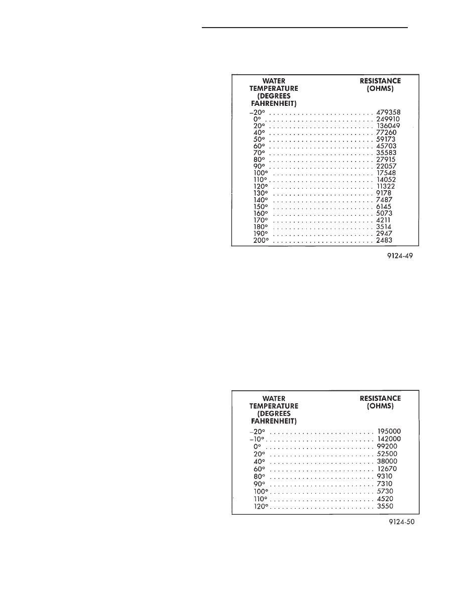
DIAGNOSTIC TROUBLE CODE 10—WATER
TEMPERATURE SENSOR FAILURE
(1) Disconnect 21-way connector at control. Mea-
sure resistance between pin #17 and pin #7. This
value will change with temperature. Refer to Tem-
perature Reference—Diagnostic Trouble Code 10
chart.
(2) Check for continuity between pin #17 and
chassis ground. If continuity is present, repair and
retest.
DIAGNOSTIC TROUBLE CODE 11—AMBIENT
TEMPERATURE SENSOR FAILURE
(1) Disconnect 21-way connector at control. With
an ohmmeter, measure the resistance between pin
#9 and pin #7. Refer to the Temperature Refer-
ence—Diagnostic Trouble Code 11 chart.
(2) Check for continuity between pin #9 and chas-
sis ground. If continuity is present, repair and retest.
TEMPERATURE REFERENCE—DIAGNOSTIC
TROUBLE CODE 10
TEMPERATURE REFERENCE—DIAGNOSTIC
TROUBLE CODE 11
24 - 80
HEATING AND AIR CONDITIONING
Ä
Нет комментариевНе стесняйтесь поделиться с нами вашим ценным мнением.
Текст