Chrysler Le Baron, Dodge Dynasty, Plymouth Acclaim. Manual — part 203
(b) Does the blower motor operate at its highest
speed ?
(c) Feel the outlet temperature. Does it get hot
and then cycle cold ?
(d) Does the air flow switch from DEFROST out-
lets and then cycle to PANEL outlets?
If you can answer NO to any of these questions,
proceed to step 4, otherwise proceed to step 5.
(4) If you answered NO to:
SYMPTOM A
The display symbols and indicators do not illumi-
nate. Diagnostic Trouble Codes are not displayed.
TEST
After self-diagnostic test is complete, select a mode
that will display the malfunction.
ACTION
If the ATC system operates properly, and the dis-
play does not, replace ATC control panel computer.
SYMPTOM B
The blower motor does not operate.
CAUTION: Stay clear of blower motor and power
module (PM) heat sink. Do not run system for more
than 10 minutes with PM removed from A/C unit.
TEST
Check all power module and blower motor connec-
tions. Use a voltmeter to test for 12 volts (ignition)
at both ends of the fuse with ignition ON. If fuse is
good, test the green wire at the blower motor connec-
tor for 12 volts (ignition) to body ground.
Turn ignition to the ON position.
With the blower motor still connected, check for 12
volts to body ground on the black/tan wire of the
blower motor two way connector.
Check for 12 volts at the Power Module pin #4
(BK/TN).
Check for continuity from the Power Module pin
#3 (BK) to chassis ground.
Replace the Power Module.
ACTION
If 12 volts is not detected, repair feed circuit. Refer
to the Front Wheel Drive Car-Wiring Diagrams Ser-
vice Manual.
If 12 volts is not detected, repair wires of the
blower motor or replace the blower motor.
If 12 volts is not present, repair wire from the
blower motor connector to the Power Module.
If circuit is open, repair ground circuit of the Power
Module.
Replace the Power Module (power transistor open).
SYMPTOM C
The outlet air temperature does not become hot
and then cycle to cold during self-test operation. Di-
agnostic Trouble Codes are not displayed.
TEST/ACTION
Make sure the blend-air door is properly attached
to the actuator.
If cold air is not discharged from the outlets, check
the base A/C refrigerant system.
Make sure heating operation works correctly, (wa-
ter level, thermostat, heater hoses, heater core, etc.).
SYMPTOM D
Air does not flow from DEFROST outlets and then
cycle to PANEL outlets during self-test operation.
TEST/ACTION
Check linkages from the mode door actuator for
binding.
Check for proper door travel in the unit.
(5) The computer will do one of two things:
• Will return to the control settings that were se-
lected before the Diagnostic Test was started. This
means the test is over. If Diagnostic Trouble Codes
did not occur, and answers to questions (a), (b), (c),
and (d) were YES, the entire system is operating cor-
rectly.
• The blower motor will stop and the computer will
flash a Diagnostic Trouble Code number from 01
through 28. Record the number and then depress the
PANEL button to advance to the next test. If the
ATC control flashes one or more codes 23 to 28, the
digits on the display will flash alternating Zeros. If
you do nothing, these codes will remain stored within
the ATC control computer. After all repairs have
been made erase fault codes. Refer to Erasing Diag-
nostic Trouble Codes 23 through 28 from ATC Con-
trol in this section.
Repair all Diagnostic Trouble Codes in the order
that they have been indicated, and then retest the
system. If any blend door test fails, all remaining
blend door tests will be skipped. IF any mode door
tests fail, all remaining mode door tests will be
skipped.
Diagnostic Test can be stopped at any time by de-
pressing any button other than PANEL.
DIAGNOSTIC TROUBLE CODE DEFINITIONS
Non-computer aided diagnostics should be per-
formed first. Hood of vehicle should be closed during
the diagnostic test to keep engine heat from effecting
the ambient temperature sensor.
Also refer to the wiring Pin out charts.
• DIAGNOSTIC TROUBLE CODE 1
Involves the wiring or the ATC control head.
• DIAGNOSTIC TROUBLE CODES 2, 13, 14, 15,
20, and 23
Ä
HEATING AND AIR CONDITIONING
24 - 73
Involves the wiring, blend-air door actuator, or the
ATC control head.
• DIAGNOSTIC TROUBLE CODES 3, 16, 17, 18, 19,
and 24
Involves the wiring, mode door actuator, or the ATC
control head.
• DIAGNOSTIC TROUBLE CODE 4
Involves the wiring, blend-air door actuator, mode
door actuator, fresh/recirc. door actuator, or the ATC
control head.
• DIAGNOSTIC TROUBLE CODE 5
Involves the wiring, fresh/recirc. door actuator, or the
ATC control head.
• DIAGNOSTIC TROUBLE CODE 6
Involves the compressor circuit signal wiring, or the
ATC control head.
• DIAGNOSTIC TROUBLE CODE 7
Involves the blower wiring, power module, or the
ATC control head.
• DIAGNOSTIC TROUBLE CODES 8, 21, 22
Requires replacing the ATC control head.
• DIAGNOSTIC TROUBLE CODES 9, and 27
Involves the wiring, sun sensor, or the ATC control
head.
• DIAGNOSTIC TROUBLE CODES 10, and 28
Involves the wiring, water temperature sensor, or the
ATC control head.
• DIAGNOSTIC TROUBLE CODES 11, and 25
Involves the wiring, ambient temperature sensor, or
the ATC control head.
• DIAGNOSTIC TROUBLE CODES 12, and 26
Involves
the
wiring,
in-car
temperature
sensor/aspirator, or the ATC control head.
DIAGNOSTIC TROUBLE CODE SERVICE PROCE-
DURES
The control keyboard will not function if pins
7, 9, 17, 19, or 20 of the 21-way wiring connector
are shorted to battery voltage.
For electrical pin numbers, refer to the wiring Pin
out charts (Figs. 1, 2, 3, 4, 5, or 6).
DIAGNOSTIC TROUBLE CODE 1—OUTPUT
FAILURE WITH ALL OUTPUTS LOW
(1) Remove pin #2 from 21-way connector on control
and retest system. If code 01 does not appear, the
control is good.
Disconnect 21-way connector from control. With an
ohmmeter, measure the resistance between pin #2 and
pin #12 of 21-way. This should be between 2,600 and
2,800 ohms. If yes, the power module is good.
Source of voltage on pin #2 is in the wiring. Repair
and retest system.
(2) Remove pin #13 from 21-way connector on con-
trol and retest system. If code 01 does not appear, the
control is good. Locate source of voltage on pin #13.
Repair and retest system.
(3) Remove pin #5 from 21-way connector on control
and retest system. If code 01 does not appear, the
control is good. Locate source of voltage on pin #5.
Repair and retest system.
(4) Remove pin #6 from 21-way connector on control
and retest system. If code 01 does not appear, the
control is good. Locate source of voltage on pin #6.
Repair and retest system.
(5) Remove pin #15 from 21-way connector on con-
trol and retest system. If code 01 does not appear, the
control is good. Locate source of voltage on pin #15.
Repair and retest system.
DIAGNOSTIC TROUBLE CODE 2—BLEND AC-
TUATOR DRIVE SIGNAL NOT HIGH
If both Diagnostic Trouble Codes 2 and 3 occur
simultaneously, do both procedures. There is
typically only 1 failure.
(1) Disconnect terminal #6 on the ATC control 21-
way connector and retest the system. Note that remov-
ing this terminal may generate additional Diagnostic
Trouble Codes. Disregard these at this time.
(2) If Diagnostic Trouble Code 2 reappears, replace
control.
(3) If code 2 does not reappear, the problem is a
shorted blend door actuator motor or a short to ground
in circuit 33 (pin #6).
(4) Remove 21-way connector and check for continu-
ity from pin #6 to chassis ground. There should not be
any continuity. If continuity is there, repair wiring and
retest.
(5) Check resistance across pins #6 and #4 of the
21-way for a shorted actuator motor. Resistance should
be between 20 and 50 ohms. If not correct, replace
actuator.
DIAGNOSTIC TROUBLE CODE 3—MODE AC-
TUATOR DRIVE SIGNAL NOT HIGH
If both Diagnostic Trouble Codes 2 and 3 occur
simultaneously, do both procedures. There is
typically only 1 failure.
(1) Disconnect terminal #5 on the ATC control 21-
way connector and retest the system. Removing this
terminal may generate additional Diagnostic Trouble
Codes. Disregard these at this time.
(2) If Diagnostic Trouble Code 3 reappears, replace
control.
(3) If code 3 does not reappear, the problem is a
shorted mode door actuator motor, or a short to ground
in circuit #35 (pin #5).
(4) Remove 21-way and check for continuity from pin
#5 to chassis ground. There should not be any continu-
ity. If continuity is there, repair wiring and retest.
24 - 74
HEATING AND AIR CONDITIONING
Ä
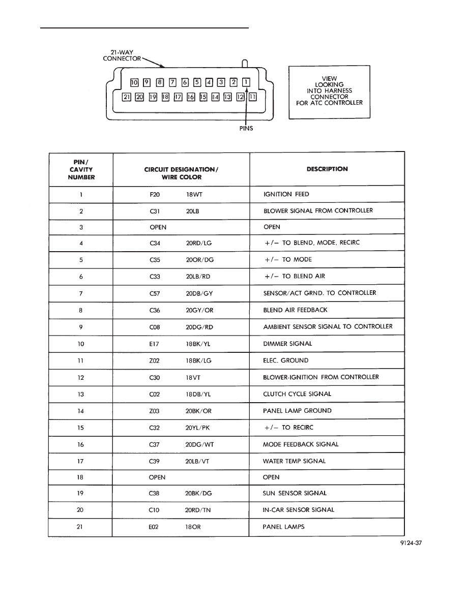
Fig. 1 Pin outs for 21-way Connector at ATC Computer Connector
Ä
HEATING AND AIR CONDITIONING
24 - 75

Fig. 2 Pin outs for 14-way Connector at ATC Harness on A/C Housing
24 - 76
HEATING AND AIR CONDITIONING
Ä
Нет комментариевНе стесняйтесь поделиться с нами вашим ценным мнением.
Текст