Chrysler Le Baron, Dodge Dynasty, Plymouth Acclaim. Manual — part 93
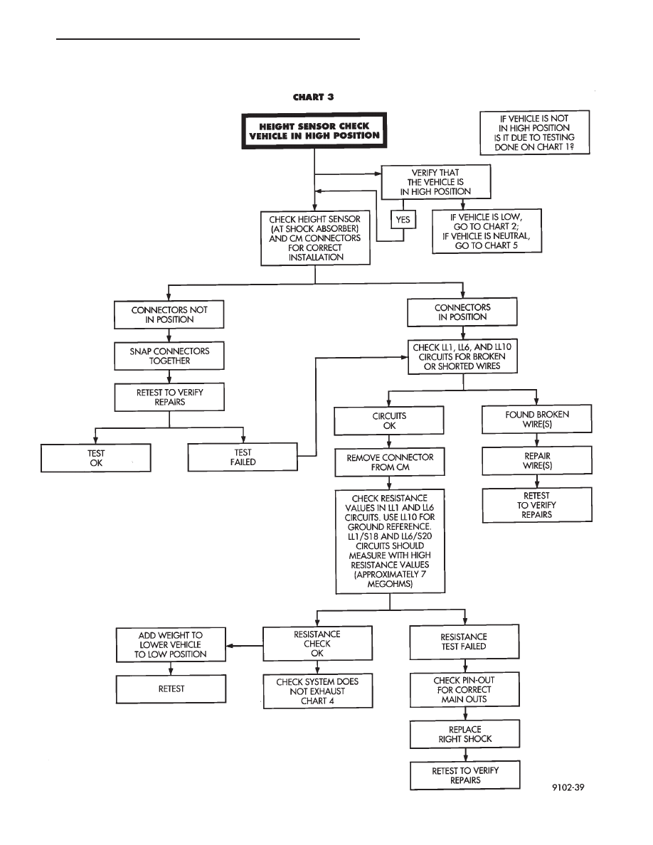
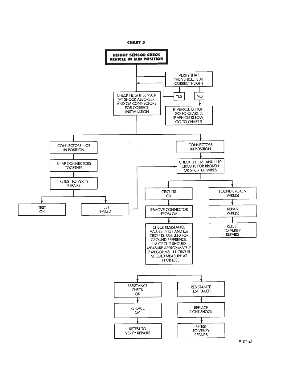
AUTOMATIC AIR LOAD LEVELING DIAGNOSTICS
Ä
SUSPENSION AND DRIVESHAFTS
2 - 69

AUTOMATIC AIR LOAD LEVELING DIAGNOSTICS
2 - 70
SUSPENSION AND DRIVESHAFTS
Ä
AUTOMATIC AIR LOAD LEVELING DIAGNOSTICS
Ä
SUSPENSION AND DRIVESHAFTS
2 - 71
CONTROL MODULE
REMOVAL
(1) Disconnect negative battery cable.
(2) Remove right side trunk trim panel.
(3) Remove electrical connectors from control mod-
ule and relay (Fig. 9).
(4) Remove control module mounting screws and
remove assembly.
INSTALLATION
(1) Install relay on the control module mounting
bracket (if required).
(2) Place control module in mounting position.
(3) Install mounting screws and tighten to 2-3 N
Im
(19-29 in. lbs.).
(4) Install control module and relay wiring connec-
tors (Fig. 9).
(5) Install right side trunk trim panel.
(6) Connect negative battery cable.
COMPRESSOR RELAY
REMOVAL
(1) Remove right side trunk trim panel.
(2) Remove electrical connector from relay.
(3) Remove relay from control module mounting
bracket by prying out on locating clip (Fig. 10).
INSTALLATION
(1) Push relay onto bracket (relay will Lock into
position).
(2) Install electrical connector.
(3) Install trim panel.
RIGHT SHOCK ABSORBER (WITH HEIGHT
SENSOR)
REMOVAL
(1) Disconnect negative battery cable.
(2) Raise vehicle, see Hoisting, Group 0.
(3) Remove tire assembly.
(4) Disconnect height sensor connector, located on
right rear frame rail.
(5) Remove both air lines connected to shock ab-
sorber ports.
(6) Remove shock, see Shock Absorbers, Removal.
INSTALLATION
(1) Install shock assembly, see Shock Absorbers,
Installation.
(2) Route height sensor wire through clip on shock
bracket, then tie strap to fuel filler tube.
(3) Snap height sensor connector into underbody
harness connector.
(4) Insert air lines.
(5) Install wheel/tire assembly.
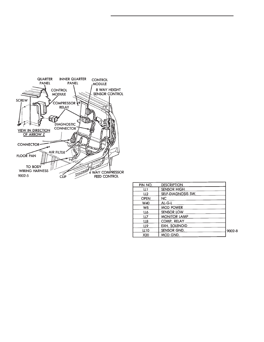
Fig. 9 Control Module and Relay Wiring
Fig. 10 Control Module Connector
2 - 72
SUSPENSION AND DRIVESHAFTS
Ä
Нет комментариевНе стесняйтесь поделиться с нами вашим ценным мнением.
Текст