Chrysler Le Baron, Dodge Dynasty, Plymouth Acclaim. Manual — part 311
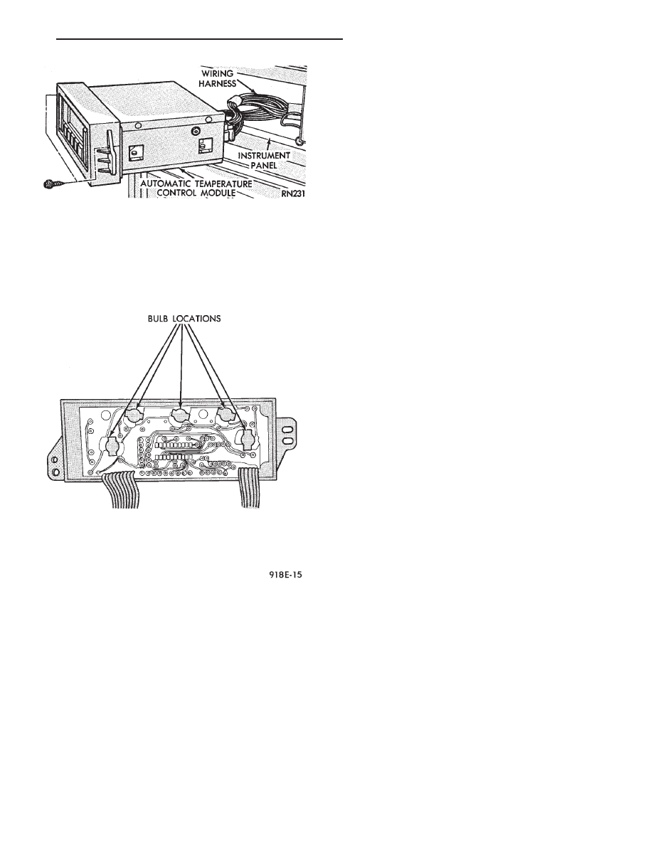
AUTOMATIC TEMPERATURE CONTROL LAMP
REMOVAL
(1) Remove automatic temperature control from in-
strument panel.
(2) Remove top cover screw and unsnap cover from
control (Fig. 30).
(3) Remove four screws that connect computer
housing to the button housing.
(4) Unsnap the button housing from the computer
housing.
(5) Remove lamps by turning in a counter clock-
wise direction and install lamps by turning in a
clockwise direction.
(6) For
installation
reverse
above
procedures.
When finish perform ATC system function test.
GLOVE BOX LAMP AND SWITCH REMOVAL
(1) Disconnect battery negative cable and isolate
or remove fuse #26 prior to removing switch or wires
may short to ground.
(2) Open glove box door.
(3) Remove lamp and test. If bad replace lamp. If
OK proceed to step 3.
(4) Carefully pry switch from its mounting surface
with tip of a small pry bar.
(5) Remove switch from glove box and disconnect
electrical leads and test for battery voltage and
ground.
(6) If OK test switch for continuity. If bad replace
switch.
(7) For installation reverse above procedures.
ENGINE COMPARTMENT NODE
The Engine Compartment Node is a microcomputer
controlled unit which informs the EVIC overhead
console via the CCD bus of outside temperature, com-
pass direction and the following warning messages:
• Brake Fluid
• Low Coolant Level
• Low Engine Oil Level
The Engine Compartment Node is located behind
the front bumper reinforcement.
For complete diagnostic procedures for the Engine
Compartment Node, refer to the AG and AJ Body Di-
agnostic Procedures Manual.
TRAVELER/EVIC REMOVAL
To test Traveler/EVIC, refer to AG, AJ Body Diag-
nostic Procedure.
(1) Remove cluster stack bezel.
(2) Remove three screws and disconnect wiring
connector.
(3) For installation reverse above procedures.
BEZEL WITH/WITHOUT MESSAGE CENTER
REMOVAL
(1) Use a straight edge tool to pry out one end of
the message center and continue to disengage six
clips along the length of the message center.
(2) Remove the message center and disconnect the
wiring.
(3) For installation reverse the above procedures.
CONSOLE SWITCH PLATE/CUBBY BOX
REMOVAL
(1) Pry up edge of switch plate or cubby box.
(2) Disconnect wiring terminal to switch plate if so
equipped.
(3) For installation reverse above procedures.
CIGAR LIGHTER REMOVAL
(1) Remove center bezel.
(2) Remove two center console attaching screws.
(3) Remove ash receptacle/cup holder.
(4) Remove two screws underneath ash receptacle/
cup holder.
(5) Remove ash receiver/bezel.
(6) Disconnect wiring connectors from lighter re-
ceptacle.
Fig. 29 Automatic Temperature Control
Fig. 30 Automatic Temperature Control Lamp
Ä
INSTRUMENT PANEL AND GAUGES
8E - 55
(7) Unscrew lighter receptacle shell from element
and remove.
(8) For installation reverse above procedures.
INSTRUMENT PANEL ROLL DOWN PROCEDURE
CAUTION: Disconnect negative battery cable, in en-
gine
compartment,
before
servicing
instrument
panel.
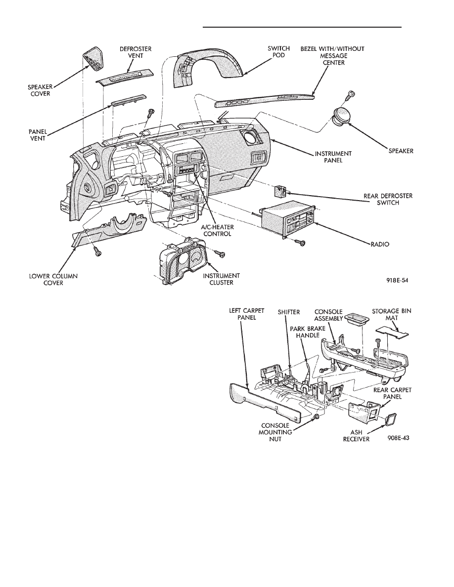
(1) Remove instrument panel center bezel (Fig.
31).
(2) Remove upper and lower steering column cov-
ers.
(3) Remove the left under panel silencer.
(4) Set parking brake.
(5) Remove console side carpet panels (Fig. 32).
(6) Remove console, refer to Group 23, Body.
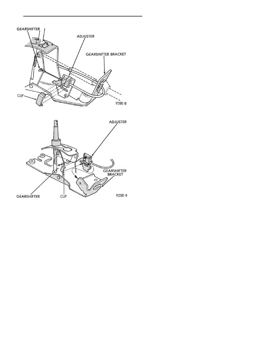
(7) Remove transmission range clip and cable loop
end from post on gear shifter (Fig. 33 and 34).
(8) Remove adjuster from tab on gear shifter
bracket. By pushing in locking knob on adjuster, and
sliding the adjuster off the tab on the gear shifter
bracket.
(a) For installation: insert transmission range
cable into adjuster and line up with the end of the
adjuster.
(b) The transmission range indicator must be ad-
justed with the gear shifter in low position.
(c) Check the gear selector indicator for proper
alignment.
(d) Attach transmission range clip to the ad-
juster to secure cable.
(9) Remove two screws and slide Air Bag Diagnos-
tic Module out of right side of instrument panel cen-
ter stack area, then disconnect wiring.
(10) Remove screw from instrument panel dimmer
module at left of steering column and lower module.
Fig. 31 Instrument Panel Components
Fig. 32 Center Console
8E - 56
INSTRUMENT PANEL AND GAUGES
Ä
(11) Remove two screws from fuse block and lower
fuse block.
(12) Remove three screws from hood release and
lower hood release handle.
(13) Remove flasher relay from bracket on center
distribution duct.
(14) Remove screw from ATC sensor motor assem-
bly and unhook from bracket if equipped.
(15) Remove the radio ground screw above flasher
relay mount.
(16) Remove center distribution duct screw from
left instrument panel lower brace, then remove four
screws to remove left lower brace.
(17) Remove five nuts on steering column and drop
column, then remove two upper column attaching studs.
(18) Remove two screws and pull out compact disc
player or cubby box, disconnect Co-Axial cable from
compact disc player.
(19) Remove Electronic Vehicle Information Center
(E.V.I.C.) or Traveler from vehicle.
(20) Remove radio.
(21) Remove A.T.C., A/C or heater controls.
(22) Squeeze latches on side of Rear Window defog-
ger switch and remove.
(23) Snap off cluster lower trim bezel, switch pod
vent grille, speaker grilles and defroster grilles.
(24) Remove switch pod assembly.
(25) Remove cluster assembly.
(26) Remove dash speakers.
(27) Snap out bezel with or without message center
and disconnect wiring.
(28) Open glovebox door, squeeze sides and roll
glovebox completely open. Remove glovebox light
switch, and disconnect wires.
(29) Loosen right cowl side pivot bolt through
glovebox opening then close glovebox.
(30) Loosen left cowl side pivot.
(31) Remove four screw attachments at top of in-
strument panel and roll panel out.
(32) Pull wiring, antenna cable, A/C cable and vac-
uum lines out of instrument panel. Disconnect demis-
ter hose and remove instrument panel with ducts
attached.
(33) Transfer ducts and brackets onto new panel.
(34) For instrument panel roll up, reverse
above procedures.
INTERIOR LAMP REMOVAL
The Dome, Floor Console and Door Lamps operate
when the doors are open or headlamp switch is
placed in courtesy position.
DOME LAMP
(1) Pry either the forward or rearward edge of the
dome lamp to free it from retaining bracket.
(2) Pry either the forward or rearward edge of the
lens away from the bezel and replace lamp.
(3) For installation reverse above procedures.
FRONT HEADER READING LAMP
Pull lamp from headliner. Disconnect wiring and
replace lamp.
FLOOR CONSOLE LAMP
Pry along top edge of lamp and pivot lamp out of
floor console, the lens does not remove. Remove lamp
and twist out lamp socket. Replace lamp.
DOOR LAMPS
Pry along bottom edge of lamp and pivot lamp out
of door trim panel, the lens does not remove. Remove
lamp and twist out lamp socket. Replace lamp.
DOOR REFLECTORS
Pry reflector away from the door trim panel, and
replace.
TRUNK LAMP
Remove lens by prying lens out of trunk trim panel
and replace bulb.
Fig. 33 Transmission Range Cable
Fig. 34 Cable Adjustment
Ä
INSTRUMENT PANEL AND GAUGES
8E - 57
AP BODY
INDEX
page
page
Cluster and Gauge Service and Testing
. . . . . . . 58
Gauges
. . . . . . . . . . . . . . . . . . . . . . . . . . . . . . . . 61
General Information
. . . . . . . . . . . . . . . . . . . . . . . 58
Instrument Panel Replacement
. . . . . . . . . . . . . . 72
Interior Lamp Replacement
. . . . . . . . . . . . . . . . . 73
Switch and Panel Component Service
. . . . . . . . . 67
GENERAL INFORMATION
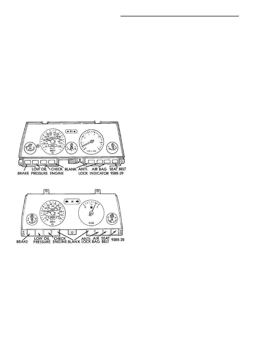
INSTRUMENT CLUSTER
There are two conventional instrument cluster as-
semblies available. The clusters incorporates mag-
netic type gauges and an electronically driven
speedometer and odometer assembly (Fig. 1 and 2).
MAGNETIC GAUGES
All gauges on the AP Body clusters are the mag-
netic type gauges. When the ignition switch is in the
OFF position each gauge, except for the voltmeter
and tachometer will show a reading. However, the
readings are only accurate when the ignition switch
is in the ON position.
TACHOMETER DRIVE MODULE
The tachometer drive module is an electronic mod-
ule used to drive the magnetic tachometer in the
high line cluster.
This module is located on top of the instrument
cluster.
ELECTRONIC DIGITAL CLOCK
The electronic digital clock is in the radio. The
clock and radio each use the display panel built into
the radio. A digital readout indicates the time in
hours and minutes whenever the ignition switch is in
the ON or ACC position.
When the ignition switch is in the OFF position, or
when the radio frequency is being displayed, time
keeping is accurately maintained.
The procedure for setting the clock varies slightly
with each radio. The correct procedure is described
under the individual radio operating instructions re-
fer to the Sound Systems Manual supplied with the
vehicle.
WARNING LAMPS AND INDICATOR LIGHTS
The instrument cluster has warning and indicators
lamps for eight different systems:
• Low oil pressure
• Brake warning
• Seat belt warning
• Malfunction indicator (check engine) lamp
• Air Bag
• High beam indicator
• Right and left turn signals.
• Anti-lock (ABS)
CLUSTER AND GAUGE SERVICE AND TESTING
CAUTION: Disconnect the negative battery cable
before servicing the instrument panel. When power
is required for test purposes, reconnect battery ca-
ble for test only. Disconnect the negative battery
cable after test and before continuing service pro-
cedures.
SENDING UNIT TEST
Check for a defective sending unit or wiring, when
a problem occurs with a cluster gauge. Do this before
disassembling the cluster.
(1) Sending units and wiring can be checked by
grounding the connector leads, at the sending unit,
in the vehicle.
(2) With the ignition in the ON position, a
grounded input will cause the fuel or temperature
gauge to read at or above maximum.
Fig. 1 Instrument Cluster With Tachometer
Fig. 2 Instrument Cluster Without Tachometer
8E - 58
INSTRUMENT PANEL AND GAUGES
Ä
Нет комментариевНе стесняйтесь поделиться с нами вашим ценным мнением.
Текст