Chrysler Le Baron, Dodge Dynasty, Plymouth Acclaim. Manual — part 309
(3) With the ignition switch ON, an open (discon-
nected sending unit wire) causes the oil, fuel or tem-
perature gauge to read below low, empty or cold
indicators.
(4) If steps 2 and 3 check OK, refer to the individ-
ual sending unit test procedures.
FUEL TANK SENDING UNIT TEST
Refer to Group 14, Fuel for test procedure.
CHECK GAUGES WARNING LAMP TESTS
The check gauges warning lamp will illuminated
when the ignition key is turned to the ON position.
The lamp will illuminate if the engine oil pressure
drops below a safe level. The check gauge lamp will
light for high engine temperature or for low voltage.
To test the system turn ignition key to the ON po-
sition. If the lamp fails to light, inspect for a broken
or disconnected wire at the oil pressure combination
sending unit, which is located at the front of the en-
gine (Fig. 13). If the wire at the connector checks
good pull connector loose from the switch terminal
and with a jumper wire ground connector to the en-
gine. With the ignition key turned to the ON posi-
tion check the warning lamp. If lamp still fails to
light, inspect for a burned lamp. If lamp still fails to
light, inspect for a burned out lamp or disconnected
socket in the cluster.
To test the switch disconnect the switch electrical
connector. Attach positive lead of an ohmmeter to
the switch terminal for the gray (GY) wire and the
negative lead to an engine ground. With the engine
off, there should be continuity in the system. Start
the engine. With the engine running, the ohmmeter
should show no continuity. If the above results are
not obtained, replace the switch.
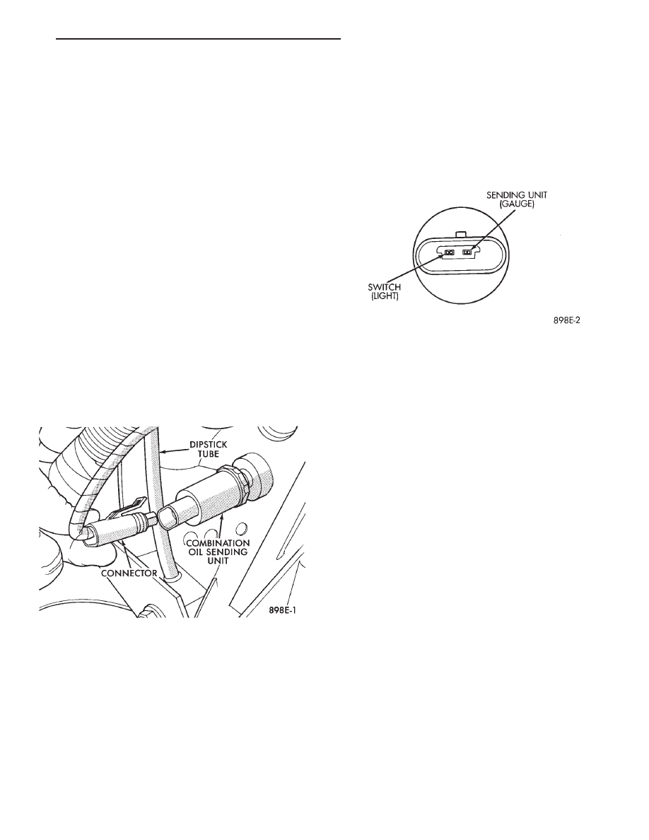
COMBINATION OIL SENDING UNIT TEST
The combination oil sending unit has two func-
tions:
(1) The normal closed circuit keeps the oil pressure
warning lamp on until there is oil pressure.
(2) The sending unit provides a resistance that
varies with oil pressure.
To test the normally closed oil lamp circuit, discon-
nect the locking connector and measure the resis-
tance between the switch terminal and the metal
housing. The ohmmeter should read 0 ohms. Start
the engine (Fig. 14).
If there is oil pressure, the ohmmeter should read
an open circuit.
To test the sending unit, measure the resistance
between the sending unit terminal and the metal
housing. The ohmmeter should read open. Start the
engine.
The ohmmeter should read between 30 to 55 ohms,
depending on engine speed, oil temperature, and oil
viscosity.
If the above results are not obtained, replace the
sending unit.
SEAT BELT WARNING SYSTEM
For testing of this system refer to Group 8U,
Chime Warning/Reminder System.
MALFUNCTION INDICATOR (CHECK ENGINE)
SYSTEM
For testing this system refer to the Body Diagnos-
tic Procedures booklet.
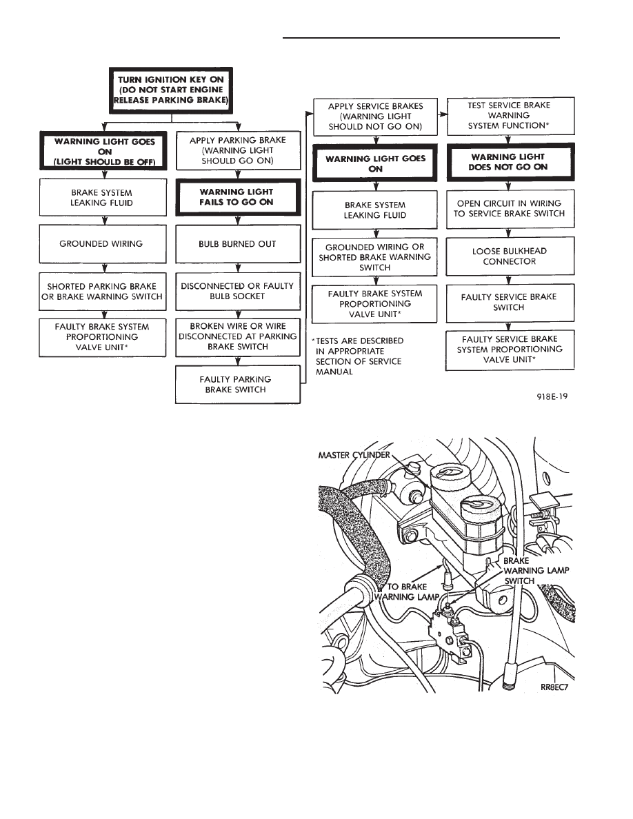
BRAKE SYSTEM WARNING LAMP TEST
The brake warning lamp illuminates when parking
brake is applied with ignition key turned ON. The
same lamp will also illuminate should one of the two
service brake systems fail when brake pedal is ap-
plied. To test system turn ignition key ON, and ap-
ply parking brake. If lamp fails to light, inspect for a
burned out lamp, disconnected socket, a broken or
disconnected wire at switch. The lamp also lights
when the ignition switch is turned to START. Refer
to Brake System Warning Lamp Diagnosis Chart
(Fig. 15).
To test service brake warning system, raise vehicle
on a hoist and open a wheel cylinder bleeder while a
Fig. 13 Combination Oil Sending Unit
Fig. 14 Combination Oil Sending Unit Test
Ä
INSTRUMENT PANEL AND GAUGES
8E - 47
helper depresses brake pedal and observes warning
lamp. If lamp fails to light, inspect for a burned out
lamp, disconnected socket, a broken or disconnected
wire at switch.
If lamp is not burned out and wire continuity is
proven, replace brake warning switch in brake line
TEE fitting mounted on frame rail in engine com-
partment below master cylinder (Fig.16).
CAUTION: If wheel cylinder bleeder was opened
check master cylinder fluid level.
SPEEDOMETER SYSTEM
The
vehicles
are
equipped
with
electronically
driven speedometer and odometer assemblies. The
unit has the same appearance as a conventional
speedometer but it eliminates the cable-driven me-
chanical system. A signal is sent from a transmis-
sion-mounted
vehicle
speed
sensor
to
the
speedometer circuitry through the wiring harness.
By eliminating the speedometer cable, instrument
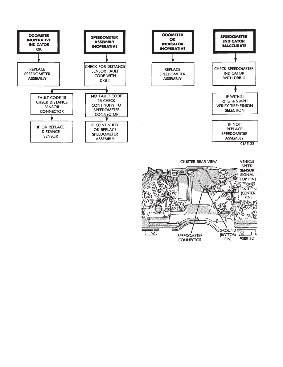
cluster service and removal is improved. Refer to Fig.
17 Speedometer Diagnosis Chart.
When the speedometer is out of calibration. The
electronic automatic transaxle vehicle speed sensor
output must be calibrated to reflect the different
combinations of equipment. The procedure is called
Pinion Factor, refer to Group 21, Transaxle for the
procedure.
Fig. 15 Brake System Warning Lamp Diagnosis
Fig. 16 Brake Warning Lamp Switch
8E - 48
INSTRUMENT PANEL AND GAUGES
Ä
SPEEDOMETER/ODOMETER ASSEMBLY
REMOVAL
(1) Remove switch pod assembly.
(2) Remove cluster, refer to Cluster Removal.
(3) Remove mask and lens assembly.
(4) Remove tachometer, turbo gauge.
(5) Remove volt, temperature, oil and fuel gauge
assemblies.
(6) Remove the speedometer/odometer assembly
from the cluster housing.
(7) Disconnect pigtail connector from the cluster
printed circuit board.
(8) For installation reverse above procedures. Lis-
ten for the pigtail connector to snap in place.
SPEEDOMETER CIRCUIT TESTING
(1) Using DRB II, check vehicle speed sensor for
speed sensor fault code and for proper speed indica-
tion. Refer to Powertrain Diagnostics Procedure
Manual; Speed Control Test (Fig. 18).
(2) Remove cluster, but do not disconnect cluster
wiring.
(3) With ignition ON check for battery voltage
across the ignition pin and ground pin of speedome-
ter connector.
(4) Check for continuity from vehicle speed sensor
signal pin to connector at speed sensor.
(5) Check cluster to body for continuity to ground.
(6) If all these tests prove good, replace speedome-
ter.
VEHICLE SPEED SENSOR REPLACEMENT
(1) Remove harness connector from sensor and
make sure weather seal is on harness connector.
(2) Remove sensor retaining bolt (Fig. 19).
(3) Pull sensor and pinion gear assembly out of
transaxle. If necessary carefully pry loose with a flat
blade screwdriver (Fig. 20).
(4) Remove pinion gear from sensor.
(5) For installation reverse above procedures. Seat
the sensor assembly by hand to ensure proper gear
engagement. Tighten retaining bolt to 7 N
Im (60 in.
lbs.) torque.
ELECTRONIC AUTOMATIC TRANSAXLE
VEHICLE SPEED SENSOR REPLACEMENT
The output vehicle speed sensor is located to the
left of the manual shift lever.
(1) Raise and support vehicle on safety stands.
(2) Remove vehicle speed sensor (Fig. 21).
(3) For installation, reverse above procedures.
Fig. 17 Speedometer Diagnosis
Fig. 18 Speedometer
Ä
INSTRUMENT PANEL AND GAUGES
8E - 49

VEHICLE SPEED SENSOR TEST
For testing of the vehicle speed sensor and related
components using DRB II, refer to the appropriate
Powertrain Diagnostics Test Procedure Manual.
TACHOMETER DRIVE MODULE REMOVAL
(1) Remove cluster assembly.
(2) Pull tachometer drive module from printed cir-
cuit board (Fig. 22).
(3) For installation reverse above procedures. Use
care when aligning module to printed circuit board.
PRINTED CIRCUIT BOARD REMOVAL
(1) Remove cluster assembly.
(2) Remove mounting screws securing printed cir-
cuit board to cluster housing.
(3) Remove tachometer drive module (Fig. 22).
(4) Twist out all lamp sockets.
(5) For installation reverse above procedures.
CLUSTER LAMPS REMOVAL—MECHANIAL
CLUSTER ONLY
(1) Remove cluster assembly (Fig. 23).
(2) Remove one piece integral lamp and socket
from rear of cluster.
ELECTRONIC CLUSTER
Refer to Body Diagnostic Procedures Manual when
using DRB II.
SELF DIAGNOSTIC SYSTEM
The electronic clusters have an internal diagnostic
routing to isolate problems within the cluster.
Fig. 20 Vehicle Speed Sensor and Speedometer Pinion
Fig. 21 Vehicle Speed Sensor Removal
Fig. 22 Cluster Printed Circuit Board
Fig. 19 Vehicle Speed Sensor and Connector
8E - 50
INSTRUMENT PANEL AND GAUGES
Ä
Нет комментариевНе стесняйтесь поделиться с нами вашим ценным мнением.
Текст