Chrysler Le Baron, Dodge Dynasty, Plymouth Acclaim. Manual — part 156
(3) Remove interior trim as necessary to gain ac-
cess to rear window defogger wire connector and
ground screw, if equipped.
(4) Remove vinyl roof bonnet, if equipped.
WARNING: WEAR EYE AND HAND PROTECTION
WHEN HANDLING SAFETY GLASS. PERSONAL IN-
JURY CAN RESULT.
CAUTION: Do not damage body or trim finish when
cutting out glass or applying fence primer.
(5) Cut the urethane around the perimeter of the
rear window glass. Refer to Windshield section of
this group for proper procedures.
(6) Separate the rear window from the vehicle.
INSTALLATION
(1) Prepare the work area, window fence, and glass
the same way as described in the Windshield section
of this group.
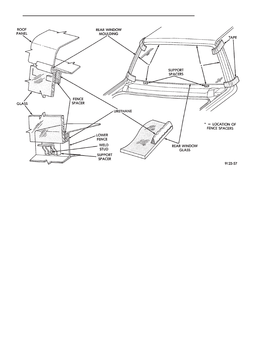
(2) Place the fence spacers at the locations shown
(Fig. 52).
(3) Apply a 10 mm (0.4 in.) bead of urethane
around the perimeter of the glass.
(4) Install the glass in the same manner described
in the Windshield section of this group.
(5) Install the rear window moulding in the gap
between the glass and the roof panel.
(6) Secure moulding and glass in position with
suitable tape. Remove tape after urethane has cured.
(7) Connect rear window defogger wiring. Install
interior trim and rear deck filler panel.
(8) After urethane has cured, water test rear win-
dow to verify repair. Verify rear window defogger op-
eration, see Group 8N, Rear Window Defogger.
TRUNK LID
REMOVAL (FIG. 53)
(1) Raise trunk lid to full up position.
(2) Disconnect the trunk lamp wire connector.
(3) Mark all bolt and hinge attachment locations
with a grease pencil or other suitable device to pro-
vide reference marks for installation. When install-
ing trunk lid, align all marks and secure bolts. The
trunk lid should be aligned to 4 mm (0.160 in.) gap
to the quarter panels and flush across the top sur-
faces along quarter panels.
(4) Remove the top trunk lid to hinge attaching
bolts and loosen the bottom bolts until they can be
removed by hand.
(5) With assistance of a helper at the opposite side
of the vehicle to support the trunk lid, remove the
Fig. 52 Rear Window Glass
Ä
AA-BODY
23 - 33

bottom trunk lid to hinge attaching bolts. Separate
the trunk lid from the vehicle.
INSTALLATION
Reverse the preceding operation.
TRUNK LID HINGE
REMOVAL (FIG. 54)
(1) Remove rear deck filler panel.
(2) Disconnect trunk lid lift torsion bars from
hinges.
(3) Mark all attaching bolt, nut, and component lo-
cations with a suitable marking device. Use marks
as a reference when installing hinge.
(4) Remove bolts holding trunk lid to hinge.
(5) Remove nuts and bolts holding hinge to closure
panel below rear window glass.
(6) Separate hinge from vehicle.
INSTALLATION
Reverse the preceding operation.
TRUNK LID TORSION BAR
REMOVAL (FIG. 54)
(1) Raise and support trunk lid in the full up posi-
tion.
(2) Remove trunk lining as necessary to gain ac-
cess to torsion bars.
(3) Disengage adjusting end of torsion bar from the
slot in the tension adjustment bracket.
(4) Pivot torsion bar out of lift arm swivel.
(5) Disconnect torsion bar from hinge.
INSTALLATION
Reverse the preceding operation.
TRUNK LID LATCH
REMOVAL (FIG. 55)
(1) Raise trunk lid to the full up position.
(2) Remove screws holding trim cover to latch and
separate cover from vehicle.
(3) Disconnect remote release cable from latch.
(4) Disconnect trunk lock linkage rod from trunk
latch, on AA-P and D models.
(5) Remove bolts holding latch to trunk lid and
separate latch from vehicle.
INSTALLATION
Insert trunk lock chill into latch release driver, on
AA-C models and reverse the preceding operation.
TRUNK LID LOCK
REMOVAL (FIG. 56)
AA-P/D MODELS
(1) Remove trunk lid tail light assembly. Refer to
Group 8L, Lamps for proper procedures.
(2) Remove screws holding latch release linkage
cover to trunk lid and separate cover from vehicle.
(3) Disconnect linkage rod from lock cylinder lever.
(4) Remove nut holding lock cylinder to trunk lid
and separate lock from vehicle.
INSTALLATION
Reverse the preceding operation.
Fig. 53 Trunk Lid
Fig. 54 Trunk Lid Hinge
Fig. 55 Trunk Lid Latch
23 - 34
AA-BODY
Ä
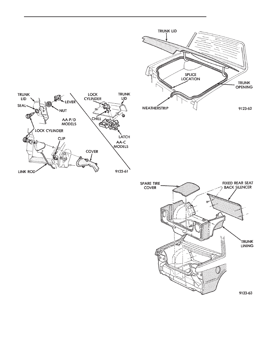
REMOVAL (FIG. 56)
AA-C MODELS
(1) Remove trunk lid tail light assembly. Refer to
Group 8L, Lamps for proper procedures.
(2) Remove trunk latch.
(3) Remove bolts holding lock cylinder and chill to
trunk lid and separate the lock from the vehicle.
INSTALLATION
Reverse the preceding operation.
TRUNK OPENING WEATHERSTRIP
REMOVAL(FIG. 57)
(1) Raise trunk lid to the full up position.
(2) Pull the weatherstrip from the pinch flange
around the trunk opening.
INSTALLATION
A new trunk lid opening weatherstrip should be
heated to approximately 38° C (100° F) before install-
ing. The weatherstrip butt splice should be located at
the center rear of trunk opening. Reverse the re-
moval operation. After weatherstrip has been in-
stalled, close trunk lid and allow weatherstrip to
cool. The weatherstrip will form to the trunk lid con-
tour as it cools.
TRUNK LINING
REMOVAL (FIG. 58)
(1) Remove spare tire and emergency jack from the
spare tire well.
(2) Remove screws holding trunk lining to tail clo-
sure panel.
(3) Remove screws holding trunk lining to inner
quarter panels.
(4) Remove push-in fasteners holding lining to rear
seat
bulkhead.
Remove
seat
back
silencer,
if
equipped.
(5) Remove push-in fasteners holding rear seat back
carpet covers to floor pan, if equipped with 60/40 rear
seat back.
(6) Fold trunk lining inward, away from quarter
panels and remove lining from vehicle.
INSTALLATION
Route the fuel fill door emergency release cable
around rear edge of trunk lining side panel and reverse
the removal operation.
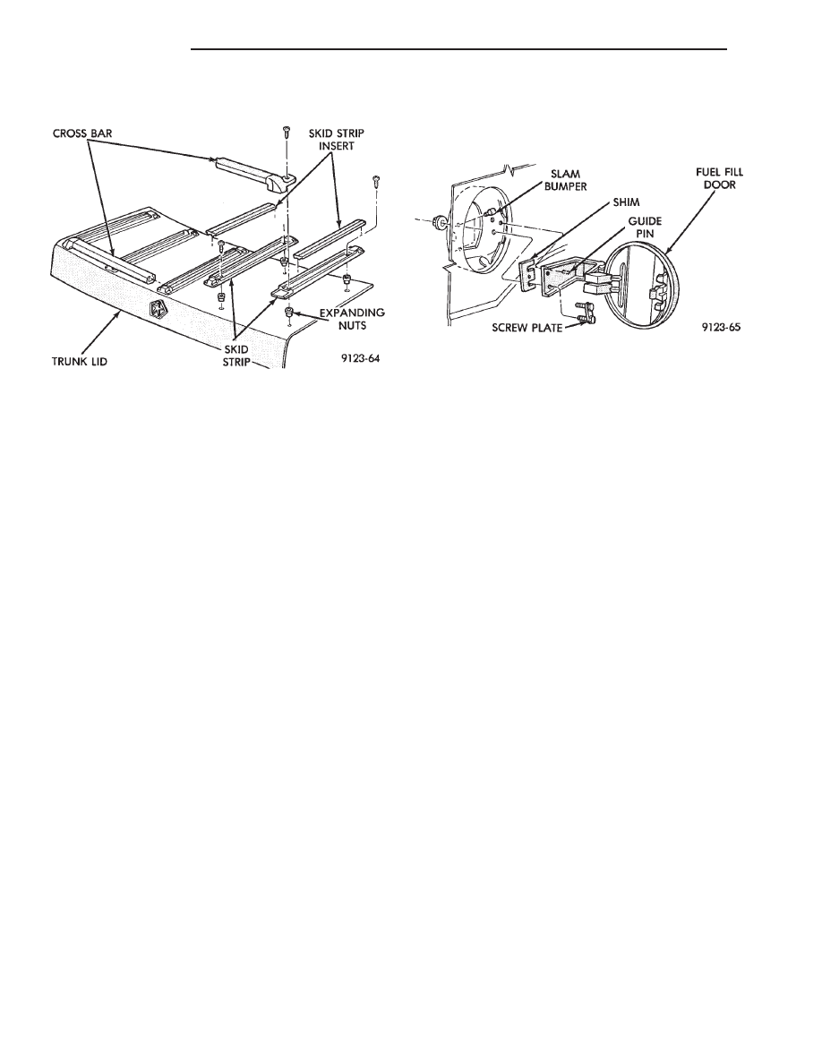
TRUNK LID LUGGAGE RACK
REMOVAL (FIG. 59)
(1) Remove screws holding cross bar to outboard
skid strips.
(2) Pry rubber inserts from skid strips.
(3) Remove screws holding skid strips to trunk lid.
Fig. 56 Trunk Lid Lock
Fig. 57 Trunk Opening Weatherstrip
Fig. 58 Trunk Lining
Ä
AA-BODY
23 - 35
INSTALLATION
Reverse the preceding operation
FUEL FILL DOOR
REMOVAL (FIG. 60)
(1) Open fuel fill door.
(2) Separate trunk lining from right quarter panel.
(3) Remove nuts holding fuel fill door to quarter
panel.
(4) Separate fuel fill door from quarter panel open-
ing.
INSTALLATION
Reverse the preceding operation. Align to achieve
equal spacing around fuel fill door and flush to the
quarter panel.
Fig. 59 Trunk Lid Luggage Rack
Fig. 60 Fuel Fill Door
23 - 36
AA-BODY
Ä
Нет комментариевНе стесняйтесь поделиться с нами вашим ценным мнением.
Текст