Chrysler Le Baron, Dodge Dynasty, Plymouth Acclaim. Manual — part 154
WHEEL OPENING AND BODY SIDE MOULDING
REMOVAL AND INSTALLATION (FIG. 38)
FRONT FENDER
(1) Remove screws holding wheel opening mould-
ing to front fender.
(2) Pry bottom of body side moulding from clip on
front fender using a suitable trim stick. Lift mould-
ing from clip and separate from fender.
(3) Replace damaged moulding clip weld studs
with repair screws. Paint bare metal surfaces behind
moulding to avoid rust.
(4) Position moulding in wheel opening and start
top center screw of wheel opening moulding.
(5) Hook top of body side moulding over clip and
snap bottom of moulding onto clip.
(6) Install screws around wheel opening.
DOORS
(1) Pry bottom of body side moulding from clips on
door using a suitable trim stick. Lift moulding from
clip and separate from door.
(2) Replace damaged moulding clip weld studs
with repair screws. Paint or undercoat bare metal
surfaces behind moulding to avoid rust.
(3) Position moulding on door in design location.
(4) Hook top of moulding over clips and snap bot-
tom of moulding onto clips.
QUARTER PANEL
(1) Remove screws holding wheel opening mould-
ing to quarter panel.
(2) Pry bottom of body side moulding from clip on
quarter panel using a suitable trim stick. Lift moul-
ding from clip and separate from fender.
(3) Replace damaged moulding clip weld studs
with repair screws. Paint or undercoat bare metal
surfaces behind moulding to avoid rust.
(4) Position moulding in wheel opening and start
top center screw of wheel opening moulding.
(5) Hook top of body side moulding over clip and
snap bottom of moulding onto clip.
(6) Install screws around wheel opening.
APPLIQUE MOULDING AND RETAINER
REMOVAL (FIG. 38)
(1) Remove screws holding applique to rocker
panel from under vehicle.
(2) Lift applique upward to separate from retain-
ing channel.
(3) Remove pop-rivets holding retainer to rocker
panel using a suitable drill.
APPLIQUE MOULDING AND RETAINER
INSTALLATION
(1) Install applique retainer on rocker panel with
pop-rivets. Paint or undercoat bare metal surfaces to
avoid rust.
(2) Hook top of applique over retainer channel and
install screws under rocker panel.
COWL PANEL TRIM AND SCUFF PLATES
COWL PANEL AND DOOR OPENING SCUFF
PLATE REMOVAL (FIG. 39)
(1) Open front door.
(2) Remove screw holding trim panel to cowl for-
ward of the front door opening.
(3) Remove screws holding scuff plate to door sill.
(4) Separate cowl panel trim and scuff plate from
vehicle.
COWL PANEL AND DOOR OPENING SCUFF
PLATE INSTALLATION
Reverse the preceding operation.
REAR DOOR OPENING SCUFF PLATE
REMOVAL (FIG. 39)
(1) Open rear door.
(2) Remove screws holding scuff plate to door sill.
(3) Separate scuff plate from vehicle.
REAR DOOR OPENING SCUFF PLATE
INSTALLATION
Reverse the preceding operation.
A-PILLAR AND ROOF RAIL MOULDINGS
A-PILLAR MOULDING REMOVAL (FIG. 39)
(1) Open front door.
(2) Disengage clips holding A-pillar moulding to
roof rail above door opening.
(3) Slide A-pillar moulding upward and pull rear-
ward to separate moulding from A-pillar.
A-PILLAR MOULDING INSTALLATION
Reverse the preceding operation.
REAR DOOR ROOF RAIL MOULDING
REMOVAL (FIG. 39)
(1) Open rear door.
(2) Disengage clips holding roof rail moulding to
roof rail above rear door opening.
(3) Separate moulding from vehicle.
REAR DOOR ROOF RAIL MOULDING
INSTALLATION
Reverse the preceding operation.
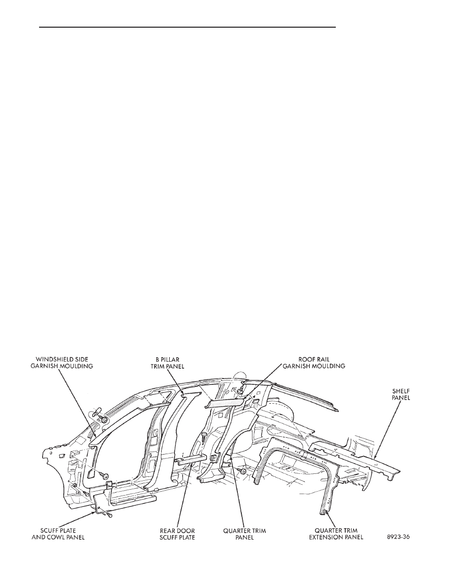
B-PILLAR TRIM PANEL
B-PILLAR TRIM PANEL REMOVAL (FIG. 39)
(1) Remove roof rail mouldings and scuff plates as
necessary.
(2) Remove shoulder harness turning loop cover.
Remove bolt holding turning loop to B-pillar.
Ä
AA-BODY
23 - 25
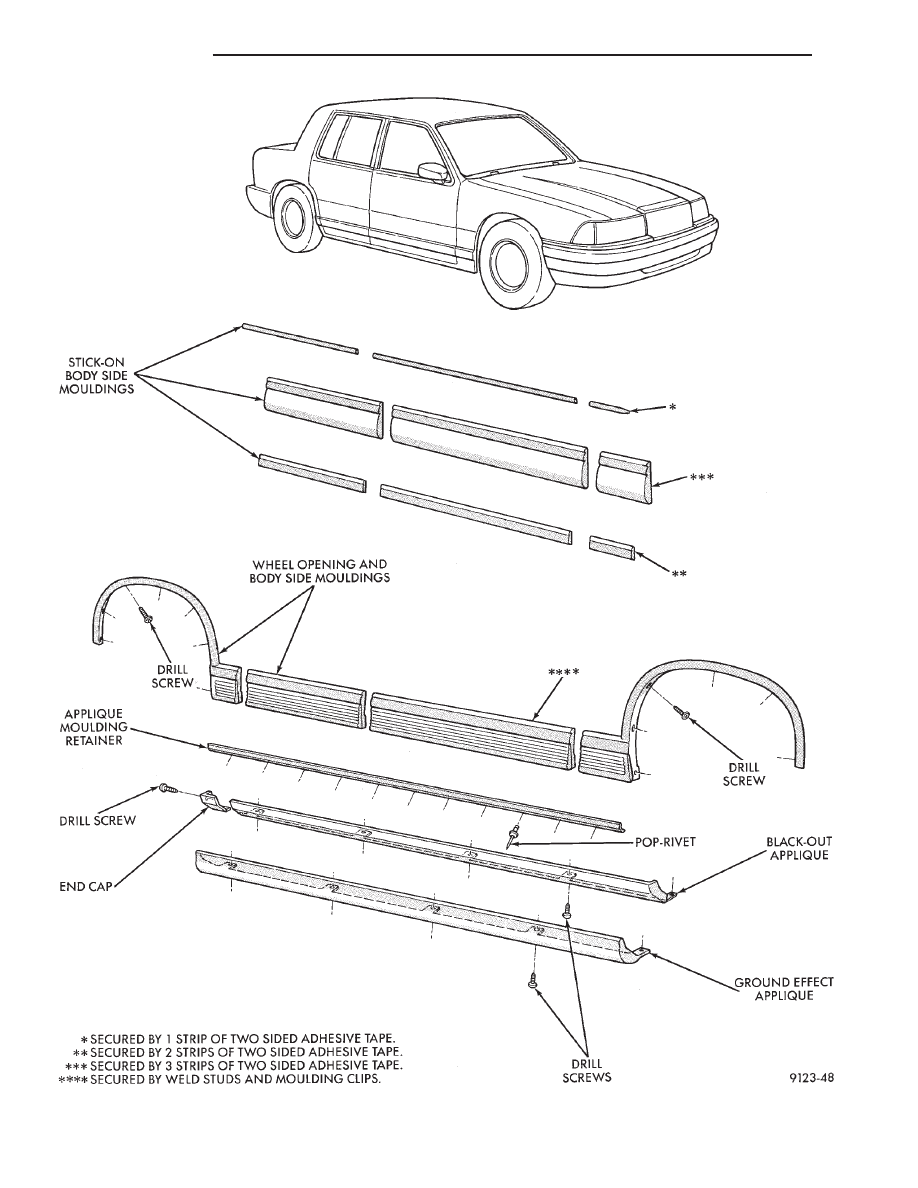
Fig. 38 Body Side Mouldings
23 - 26
AA-BODY
Ä
(3) Remove bolt holding seat belt to floor below
B-pillar.
(4) Lift B-pillar trim off door opening sill weather-
strips and push inward.
(5) Slide B-pillar trim downward as far as possible
and separate trim from B-pillar.
B-PILLAR TRIM PANEL INSTALLATION
Reverse the preceding operation.
QUARTER TRIM PANEL
REMOVAL (FIG. 39)
(1) Remove roof rail mouldings and scuff plates as
necessary.
(2) Remove shoulder harness turning loop cover.
Remove bolt holding turning loop to quarter panel.
(3) Remove rear seat cushion, back, and rear bol-
ster.
(4) Remove push-in fastener holding quarter trim
to roof rail.
(5) Remove screws holding quarter trim panel to
wheelhouse kickup.
(6) Pull trim panel forward and separate from ve-
hicle.
INSTALLATION
Reverse the preceding operation.
QUARTER EXTENSION TRIM PANEL
REMOVAL (FIG. 39)
(1) Remove rear seat cushion, back, and rear bol-
ster.
(2) Disengage clips holding expansion trim panel
to shelf panel.
(3) Separate trim panel from vehicle.
INSTALLATION
Reverse the preceding operation.
REAR SHELF TRIM PANEL
REMOVAL (FIG. 39)
(1) Remove one quarter trim panel.
(2) Remove center high mounted stop lamp cover.
Refer to Group 8L, Lamps for instructions.
(3) Disengage frog leg fasteners holding trim to
shelf panel and separate trim from vehicle.
INSTALLATION
Reverse the preceding operation.
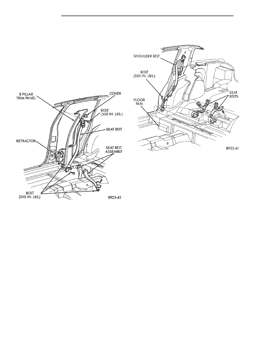
FRONT SEAT BELTS
OUTBOARD SHOULDER HARNESS/LAP BELT
REMOVAL (FIG. 40)
(1) Remove B-pillar trim panel.
(2) Remove bolt holding seat belt retractor to
B-pillar.
(3) Separate retractor from vehicle.
OUTBOARD SHOULDER HARNESS/LAP BELT
INSTALLATION
Reverse the preceding operation.
Fig. 39 Interior Mouldings, Panels, and Trim Covers
Ä
AA-BODY
23 - 27
INBOARD BUCKLE/CENTER OCCUPANT
BELTS REMOVAL (FIG. 40)
Vehicles equipped with front bucket seats with cen-
ter console do not have center occupant belts.
(1) Remove bolt holding inboard buckle/center oc-
cupant belt to floor.
(2) Disconnect seat belt sensor wire connector.
(3) Separate buckle/belt assembly from vehicle.
INBOARD BUCKLE/CENTER OCCUPANT BELT
INSTALLATION
Reverse the preceding operation.
REAR SEAT BELTS
OUTBOARD SHOULDER HARNESS/LAP BELT
REMOVAL (FIG. 41)
(1) Remove quarter trim panel.
(2) Remove bolt holding lap belt to floor at wheel-
house kickup.
(3) Remove bolt holding seat belt retractor to quar-
ter panel.
OUTBOARD SHOULDER HARNESS/LAP BELT
INSTALLATION
Reverse the preceding operation.
INBOARD BUCKLE/CENTER OCCUPANT
BELTS REMOVAL (FIG. 41)
(1) Remove rear seat cushion.
(2) Remove bolt holding inboard buckle/center oc-
cupant belt to floor.
(3) Separate buckle/belt assembly from vehicle.
INBOARD BUCKLE/CENTER OCCUPANT BELT
INSTALLATION
Reverse the preceding operation.
FRONT SEATS
REMOVAL (FIG. 42 OR 43)
(1) Position seat full forward.
(2) Remove screws holding rear track riser covers
and separate covers from tracks.
(3) On power seat track, remove outboard track
cover.
(4) On 50/50 seats, remove inboard seat belt at-
taching bolt from floor.
(5) Remove nuts holding seat track to floor.
(6) Position seat full rearward.
(7) On power seat track, remove door sill scuff
plate and disconnect wire connector.
(8) Remove bolts holding seat track to cross mem-
ber.
(9) Remove seat from vehicle.
INSTALLATION
Reverse the preceding operation.
REAR SEATS
REAR SEAT CUSHION REMOVAL
(1) Remove bolts holding cushion to floor.
(2) Push center occupant seat belts through open-
ings in cushion.
(3) Remove cushion from vehicle.
REAR SEAT CUSHION INSTALLATION
Reverse the preceding operation.
Fig. 40 Front Seat Belts
Fig. 41 Rear Seat Belts
23 - 28
AA-BODY
Ä
Нет комментариевНе стесняйтесь поделиться с нами вашим ценным мнением.
Текст