Chrysler Le Baron, Dodge Dynasty, Plymouth Acclaim. Manual — part 41
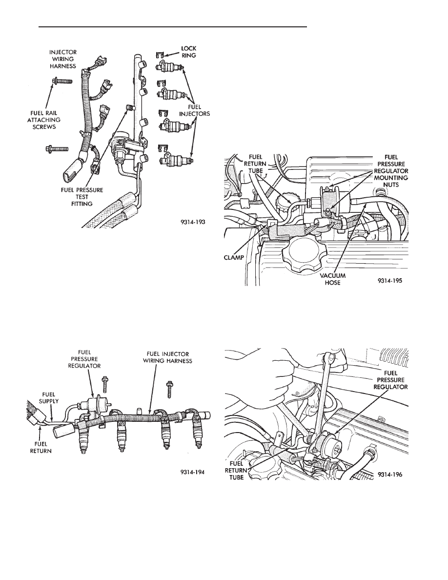
(1) Before installing an injector, lubricate O-ring
with a drop of clean engine oil.
(2) Being careful not to damage the O-ring, install
injector top end into fuel rail receiver cup.
(3) Install injector lock ring by sliding open end
into slot of the injector and onto the receiver cup
ridge into the side slots of ring (Fig. 8).
(4) Repeat steps for remaining injectors.
(5) Install injector wiring harness to injectors and
fasten into wiring clips (Fig. 10).
FUEL PRESSURE REGULATOR
WARNING: RELEASE FUEL SYSTEM PRESSURE
BEFORE SERVICING FUEL SYSTEM COMPONENTS.
WHEN
SERVICING
FLEXIBLE
FUEL
VEHICLES,
WEAR METHANOL RESISTANT GLOVES AND EYE
PROTECTION AND AVOID BREATHING FUMES. DO
NOT ALLOW METHANOL/GASOLINE MIXTURES TO
CONTACT SKIN. SERVICE VEHICLES IN WELL VEN-
TILATED AREAS AND AVOID IGNITION SOURCES.
NEVER SMOKE WHILE SERVICING THE VEHICLE.
REMOVAL
(1) Perform fuel system pressure release procedure.
(2) Disconnect negative cable from battery.
(3) Disconnect vacuum hose from fuel pressure reg-
ulator (Fig. 11).
Place a shop towel under fuel pressure regula-
tor to absorb any fuel spillage.
(4) Use 2 tubing wrenches, to loosen the line nut
on the fuel return tube (Fig. 12).
(5) Remove fuel pressure regulator mounting nuts
(Fig. 11).
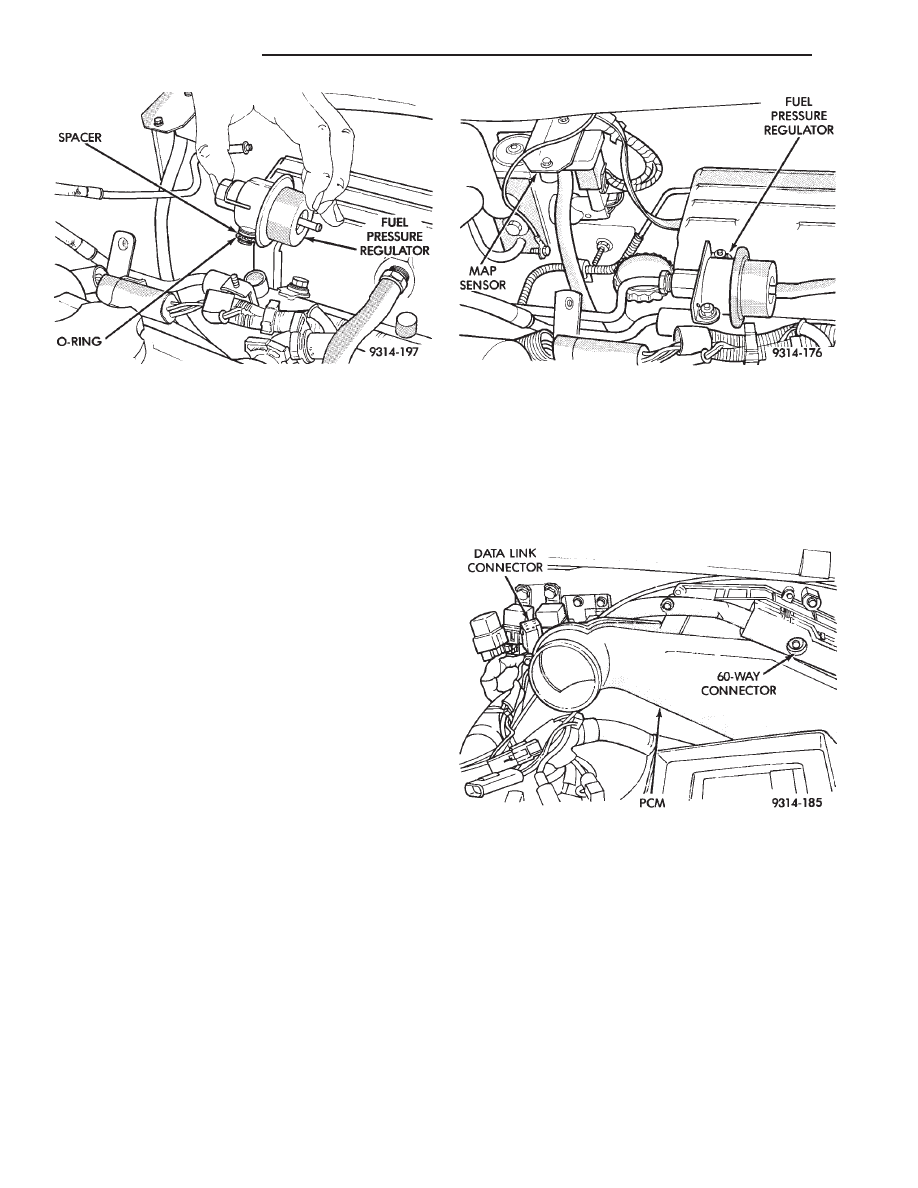
(6) Lift pressure regulator up out of fuel rail (Fig.
13). Ensure the O-ring and spacer were removed
with the regulator. Discard O-Ring.
Fig. 9 Fuel Rail and Injector Assembly
Fig. 10 Fuel Rail Assembly
Fig. 11 Servicing Fuel Pressure Regulator
Fig. 12 Removing Fuel Return Tube
Ä
FUEL SYSTEMS
14 - 81
INSTALLATION
WARNING: THE FUEL PRESSURE REGULATOR,
O-RING AND SPACER DESIGNED FOR GASOLINE
ONLY VEHICLES CANNOT BE USED ON FLEXIBLE
FUEL AA-BODY VEHICLES. WHEN SERVICING THE
FUEL SYSTEM OF A FLEXIBLE FUEL VEHICLE,
ONLY USE ORIGINAL EQUIPMENT OR EQUIVA-
LENT REPLACEMENT COMPONENTS.
(1) Lubricate new O-ring with a drop of clean en-
gine oil. Install spacer and O-ring into the receiver
cup on fuel rail (Fig. 13).
(2) Install mounting nuts. Tighten nuts to 7 N
Im
(65 in. lbs.) torque.
(3) Connect fuel return tube to pressure regulator.
Using a wrench to hold the fuel pressure regulator,
tighten the nut to 28 N
Im (150 in. lbs.) torque.
(4) Connect vacuum hose to pressure regulator. Re-
place clamp.
(5) Connect negative cable to battery.
CAUTION: When using the ASD Fuel System Test,
the Auto Shutdown (ASD) Relay remains energized
for either 7 minutes, until the test is stopped, or un-
til the ignition switch is turned to the Off position.
(6) With the DRBII scan tool, use the ASD Fuel
System Test to pressurize system and check for
leaks.
MANIFOLD ABSOLUTE PRESSURE (MAP) SENSOR
SERVICE
(1) Remove vacuum hose and remove mounting
screws from sensor (Fig. 14).
(2) Remove wiring harness and remove sensor.
(3) Reverse the above procedure for installation.
PCM SERVICE
(1) Remove air cleaner duct from PCM.
(2) Remove battery.
(3) Remove PCM mounting screws (Fig. 15).
(4) Remove 60 way wiring connector from module
and remove module.
(5) Reverse the above procedure for installation.
METHANOL CONCENTRATION SENSOR
Refer to the Fuel Delivery section of this group for
methanol concentration sensor service.
HEATED OXYGEN SENSOR (O
2
SENSOR)
The oxygen sensor is installed in the exhaust man-
ifold (Fig. 16).
CAUTION: Do not pull on the oxygen sensor wires
when disconnecting the electrical connector.
WARNING: THE EXHAUST MANIFOLD MAY BE EX-
TREMELY HOT. USE CARE WHEN SERVICING THE
OXYGEN SENSOR.
Fig. 13 Fuel Pressure Regulator
Removal/Installation
Fig. 14 Manifold Absolute Pressure Sensor
Fig. 15 PCM Removal/Installation
14 - 82
FUEL SYSTEMS
Ä
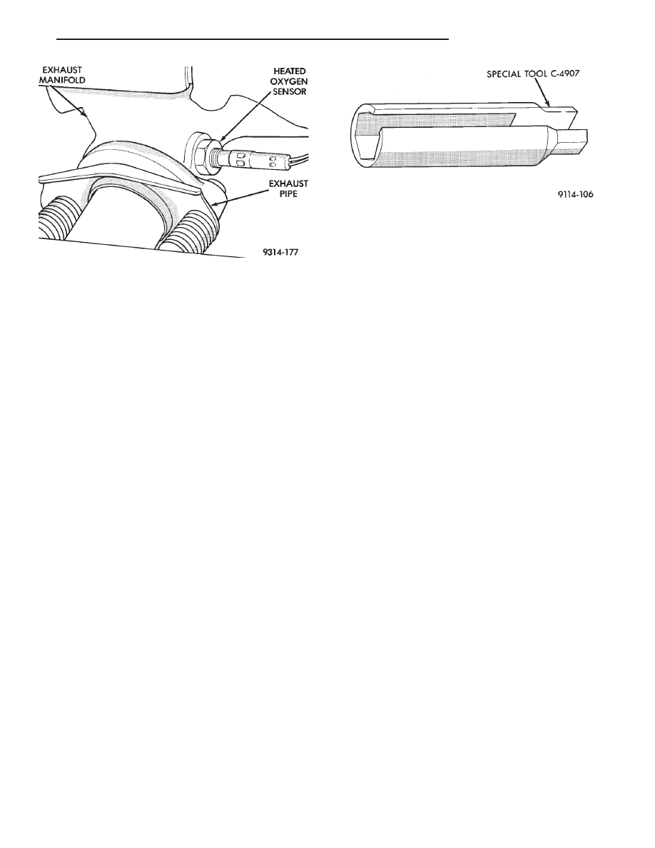
(1) Disconnect oxygen sensor electrical connector.
(2) Remove sensor using Tool C-4907 (Fig. 17).
Slightly tightening the sensor can ease removal.
When the sensor is removed, the exhaust manifold
threads must be cleaned with an 18 mm X 1.5 + 6E tap.
If using original sensor, coat the threads with Loctite
771-64 anti-seize compound or equivalent. New sen-
sors are packaged with compound on the threads and
do not require additional compound. The sensor must
be tightened to 28 N
Im (20 ft. lbs.) torque.
2.2L TURBO III MULTI-PORT FUEL INJECTION—SYSTEM OPERATION
INDEX
page
page
Air Conditioning Clutch Relay—PCM Output
. . . . 89
Air Conditioning Switch Sense—PCM Input
. . . . . 85
Auto Shutdown (ASD) Relay and Fuel Pump
Relay—PCM Output
. . . . . . . . . . . . . . . . . . . . . 89
Barometric Read Solenoid—PCM Output
. . . . . . . 90
Battery Voltage—PCM Input
. . . . . . . . . . . . . . . . 85
Brake Switch—PCM Input
. . . . . . . . . . . . . . . . . . 85
Camshaft Position Sensor—PCM Input
. . . . . . . . 85
Canister Purge Solenoid—PCM Output
. . . . . . . . 90
CCD Bus
. . . . . . . . . . . . . . . . . . . . . . . . . . . . . . 84
Charge Air Temperature Sensor—PCM Input
. . . 86
Crankshaft Position Sensor—PCM Input
. . . . . . . 87
Data Link Connector—PCM Output
. . . . . . . . . . . 91
Engine Coolant Temperature Sensor—PCM Input . 86
Fuel Injector—PCM Output
. . . . . . . . . . . . . . . . . 91
Fuel Injectors and Fuel Rail Assembly
. . . . . . . . . 94
Fuel Pressure Regulator
. . . . . . . . . . . . . . . . . . . 94
Fuel Supply Circuit
. . . . . . . . . . . . . . . . . . . . . . . 94
General Information
. . . . . . . . . . . . . . . . . . . . . . . 83
Generator Field—PCM Output
. . . . . . . . . . . . . . . 89
Heated Oxygen Sensor (O
Sensor)—PCM Input
. 88
Idle Air Control Motor—PCM Output
. . . . . . . . . . 90
Ignition Coil—PCM Output
. . . . . . . . . . . . . . . . . . 91
Knock Sensor—PCM Input
. . . . . . . . . . . . . . . . . 87
Malfunction Indicator Lamp (Check Engine)—PCM
Output
. . . . . . . . . . . . . . . . . . . . . . . . . . . . . . . 90
Manifold Absolute Pressure (Map) Sensor—PCM
Input
. . . . . . . . . . . . . . . . . . . . . . . . . . . . . . . . 87
Modes of Operation
. . . . . . . . . . . . . . . . . . . . . . . 92
Powertrain Control Module
. . . . . . . . . . . . . . . . . 84
Radiator Fan Relay—PCM Output
. . . . . . . . . . . . 91
Speed Control Solenoids—PCM Output
. . . . . . . . 91
Speed Control—PCM Input
. . . . . . . . . . . . . . . . . 88
System Diagnosis
. . . . . . . . . . . . . . . . . . . . . . . . 84
Tachometer—PCM Output
. . . . . . . . . . . . . . . . . . 91
Throttle Body
. . . . . . . . . . . . . . . . . . . . . . . . . . . . 94
Throttle Position Sensor (TPS)—PCM Input
. . . . . 88
Vehicle Speed Sensor—PCM Input
. . . . . . . . . . . 89
Wastegate Control Solenoid—PCM Output
. . . . . 91
GENERAL INFORMATION
The turbocharged multi-port electronic fuel injec-
tion system combines an electronic fuel and spark
advance control system with a turbocharged intake
system (Fig. 1). The fuel injection system is con-
trolled by the powertrain control module (PCM).
The PCM regulates ignition timing, air-fuel ratio,
emission control devices, cooling fan, charging sys-
tem, speed control, turbocharger wastegate and idle
speed. The PCM adapts its requirement to meet
changing operating conditions.
Various sensors provide the inputs necessary for
the PCM to correctly regulate fuel flow at the fuel
injector. These include the manifold absolute pres-
sure, throttle position, oxygen sensor, coolant tem-
perature, detonation, and vehicle speed sensors. In
addition to the sensors, the air conditioning clutch
switch and various relays provide important informa-
tion and system control. The outputs include the auto
shutdown relay and fuel pump relay.
All inputs to the PCM are converted into signals.
Based on these inputs the PCM adjusts air-fuel ratio,
ignition timing, turbocharger wastegate and other
Fig. 16 Heated Oxygen Sensor
Fig. 17 Oxygen Sensor Socket
Ä
FUEL SYSTEMS
14 - 83

controlled outputs. The PCM adjusts the air-fuel ra-
tio by changing injector pulse width. Injector pulse
width is the time an injector is energized.
SYSTEM DIAGNOSIS
The PCM tests many of its own input and output
circuits. If a fault is found in a major system, the in-
formation is stored in memory. Technicians can dis-
play fault information through the malfunction
indicator lamp (instrument panel Check Engine
lamp). Also, the technician can read fault informa-
tion by connecting the DRBII scan tool to the data
link connector. For diagnostic trouble code informa-
tion, refer to the 2.2L Turbo III Multi-Port Fuel In-
jection—On-Board Diagnostics section of this group.
CCD BUS
Various modules exchange information through a
communications port called the CCD Bus. The pow-
ertrain control module (PCM) transmits vehicle load
data on the CCD Bus.
POWERTRAIN CONTROL MODULE
The powertrain control module (PCM) is a digital
computer containing a microprocessor (Fig. 2). The
PCM receives input signals from various switches
and sensors that are referred to as PCM Inputs.
Based on these inputs, the PCM adjusts various en-
gine and vehicle operations through devices that are
referred to as PCM Outputs.
PCM Inputs:
• Air Conditioning Controls
• Battery Voltage
• Brake Switch
• Camshaft Position Sensor
• Crankshaft Position Sensor
• Charge Air Temperature Sensor
• Engine Coolant Temperature Sensor
• Knock Sensor
Fig. 1 Electronic Fuel Injection Components
Fig. 2 PCM
14 - 84
FUEL SYSTEMS
Ä
Нет комментариевНе стесняйтесь поделиться с нами вашим ценным мнением.
Текст