Chrysler Le Baron, Dodge Dynasty, Plymouth Acclaim. Manual — part 189
(2) The appropriate Powertrain Diagnostic Proce-
dures Manual for diagnostic information.
(3) The Compressor Clutch Diagnosis—Variable
Displacement Compressor chart in this section.
(4) On 2.2 L Turbo III engines, check for battery
voltage at the Thermal Limiter Switch located on the
compressor.
If voltage is found at the cut-off and/or thermal
limiter switch, reconnect switch. Then check for bat-
tery voltage between the compressor clutch connector
terminals.
If voltage is detected, perform A/C Clutch Coil
Tests. Refer to Clutch Coil Tests in this section.
CLUTCH COIL TESTS
(1) Verify battery state of charge. (Test indicator
in battery should be green).
(2) Connect an ammeter (0-10 ampere scale) in se-
ries with the clutch coil terminal. Use a volt meter
(0-20 volt scale) with clip leads measuring voltage
across the battery and A/C clutch.
(3) With A/C control in A/C mode and blower at
low speed, start the engine and run at normal idle.
(4) The A/C clutch should engage immediately and
the clutch voltage should be within two volts of the
battery voltage. If the A/C clutch does not engage,
test the fusible link.
(5) The A/C clutch coil is acceptable if the current
draw is 2.0 to 3.7 amperes at 11.5-12.5 volts at clutch
coil. This is with the work area temperature at 21°C
(70°F). If voltage is more than 12.5 volts, add electri-
cal loads by turning on electrical accessories until
voltage reads below 12.5 volts.
If coil current reads zero, the coil is open and
should be replaced. If the ammeter reading is 4 am-
peres or more, the coil is shorted and should be re-
placed. If the coil voltage is not within two volts of
the battery voltage, test clutch coil feed circuit for
excessive voltage drop.
COMPRESSOR
The A/C compressor may be removed and posi-
tioned without discharging the refrigerant system.
Discharging is not necessary if removing the A/C
compressor clutch/coil assembly, engine, cylinder
head, or generator.
WARNING: REFRIGERANT PRESSURES REMAIN HIGH
EVEN THOUGH THE ENGINE MAY BE TURNED OFF.
BEFORE REMOVING A FULLY CHARGED COMPRES-
SOR, REVIEW THE SAFETY PRECAUTIONS AND
WARNINGS SECTION IN THIS GROUP. DO NOT TWIST
OR KINK THE REFRIGERANT LINES WHEN REMOV-
ING A FULLY CHARGED COMPRESSOR. SAFETY
GLASSES MUST BE WORN.
REMOVAL AND INSTALLATION
(1) Disconnect NEGATIVE battery cable.
(2) Loosen and remove drive belts (Refer to Group
7, Cooling System) and disconnect compressor clutch
wire lead.
(3) Remove refrigerant lines from compressor (if
necessary).
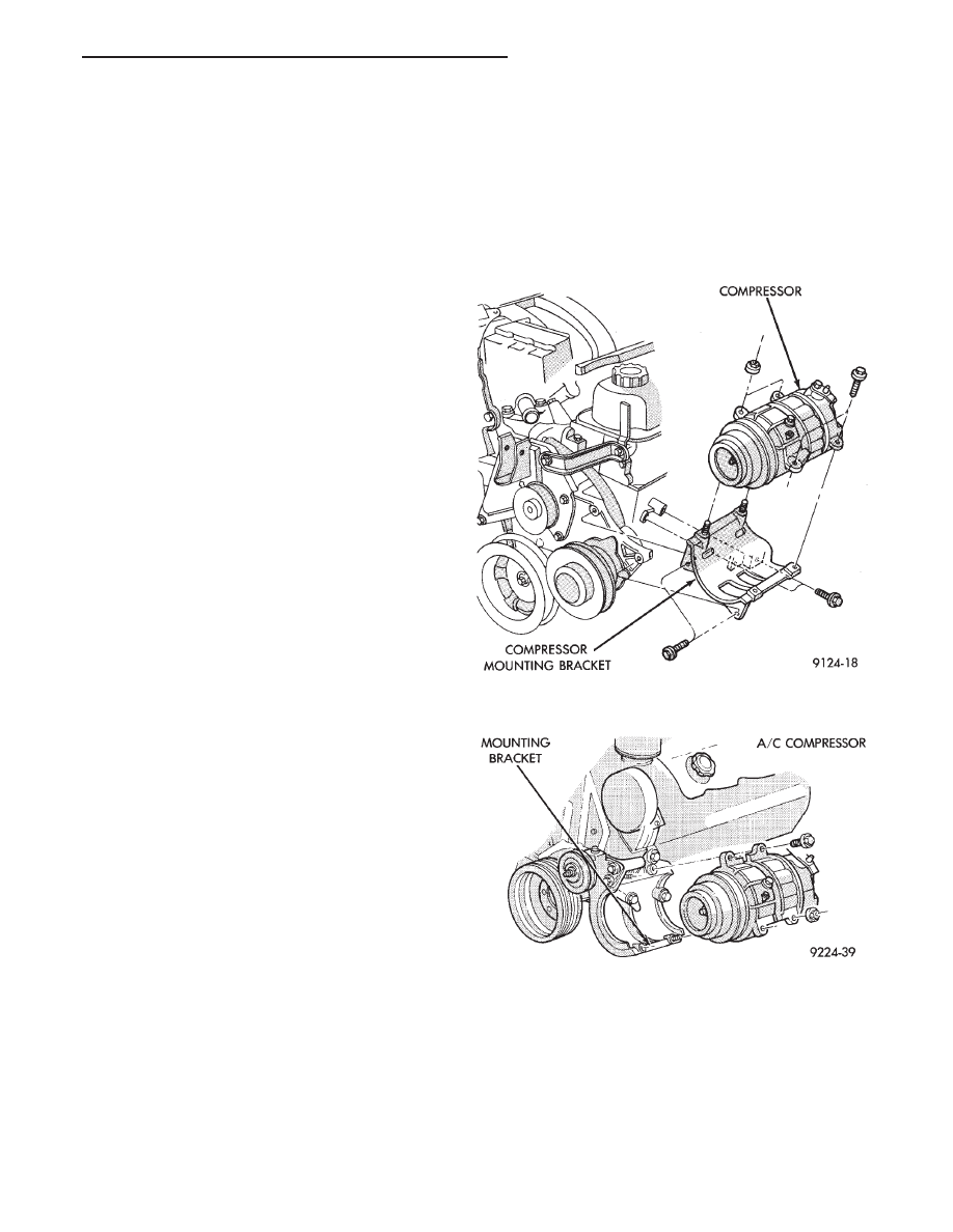
(4) Remove compressor attaching nuts and bolts
(Fig. 2 or 3).
(5) Remove compressor. If refrigerant lines were
not removed, lift compressor/clutch assembly and tie
it to a suitable component.
To install, reverse the preceding operation.
Fig. 2 A/C Compressor Removal and
Installation—3.3L Engines
Fig. 3 A/C Compressor Removal and
Installation—3.0 L Engine
Ä
HEATING AND AIR CONDITIONING
24 - 17
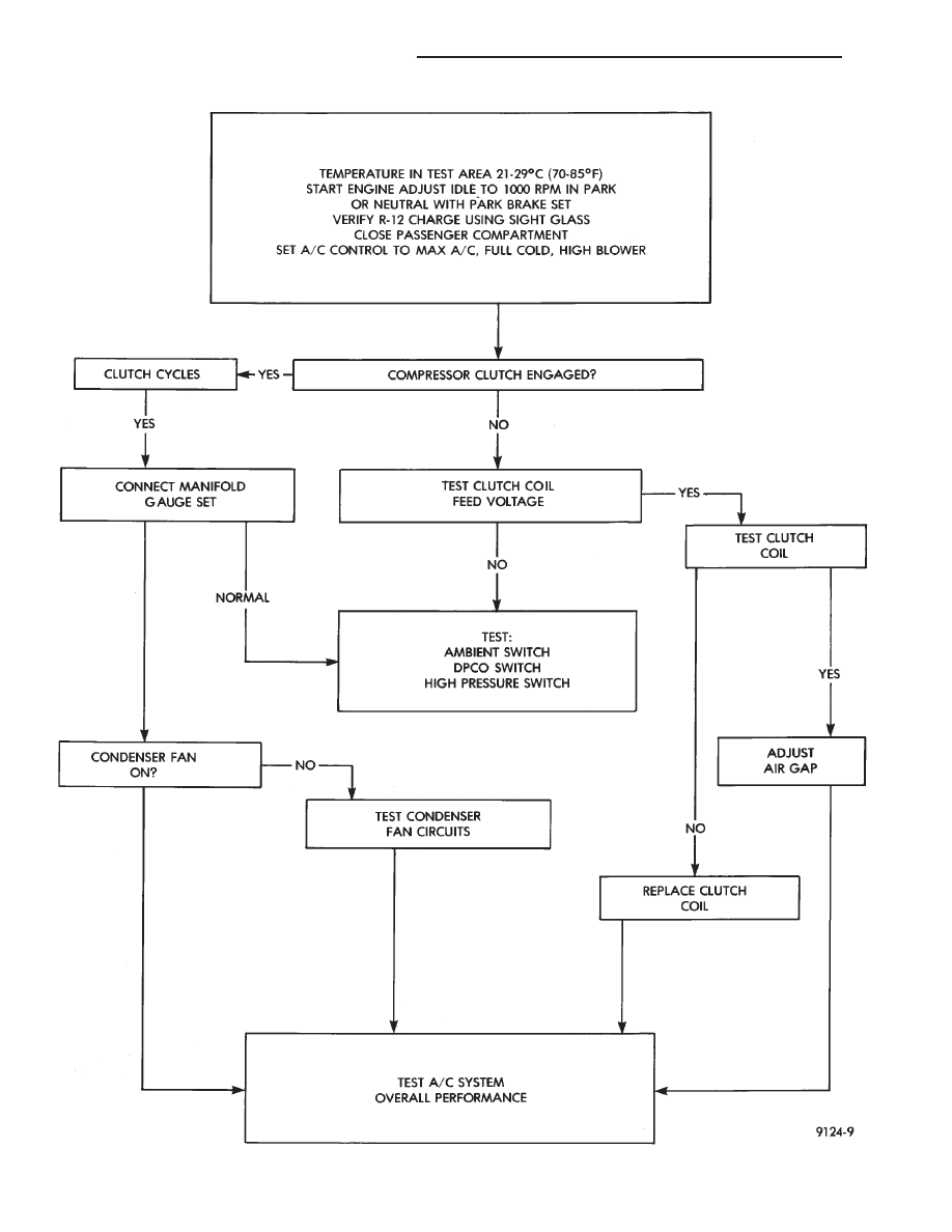
COMPRESSOR CLUTCH DIAGNOSIS—VARIABLE DISPLACEMENT COMPRESSOR—MODEL 6C17
24 - 18
HEATING AND AIR CONDITIONING
Ä
COMPRESSOR CLUTCH/COIL ASSEMBLY
Compressor
assembly
must
be
removed
from
mounting. Refrigerant removal is not necessary to
replace the clutch/coil assembly. Refer to Compressor
Removal and Installation.
On 3.0 liter engine, remove the front lower splash
shield and front engine mount through-bolt. Allow
the engine to swing down to provide access to the
front of the compressor.
On 3.3 liter engine, remove the coolant recovery
bottle to provide access the front of the compressor.
REMOVAL AND INSTALLATION
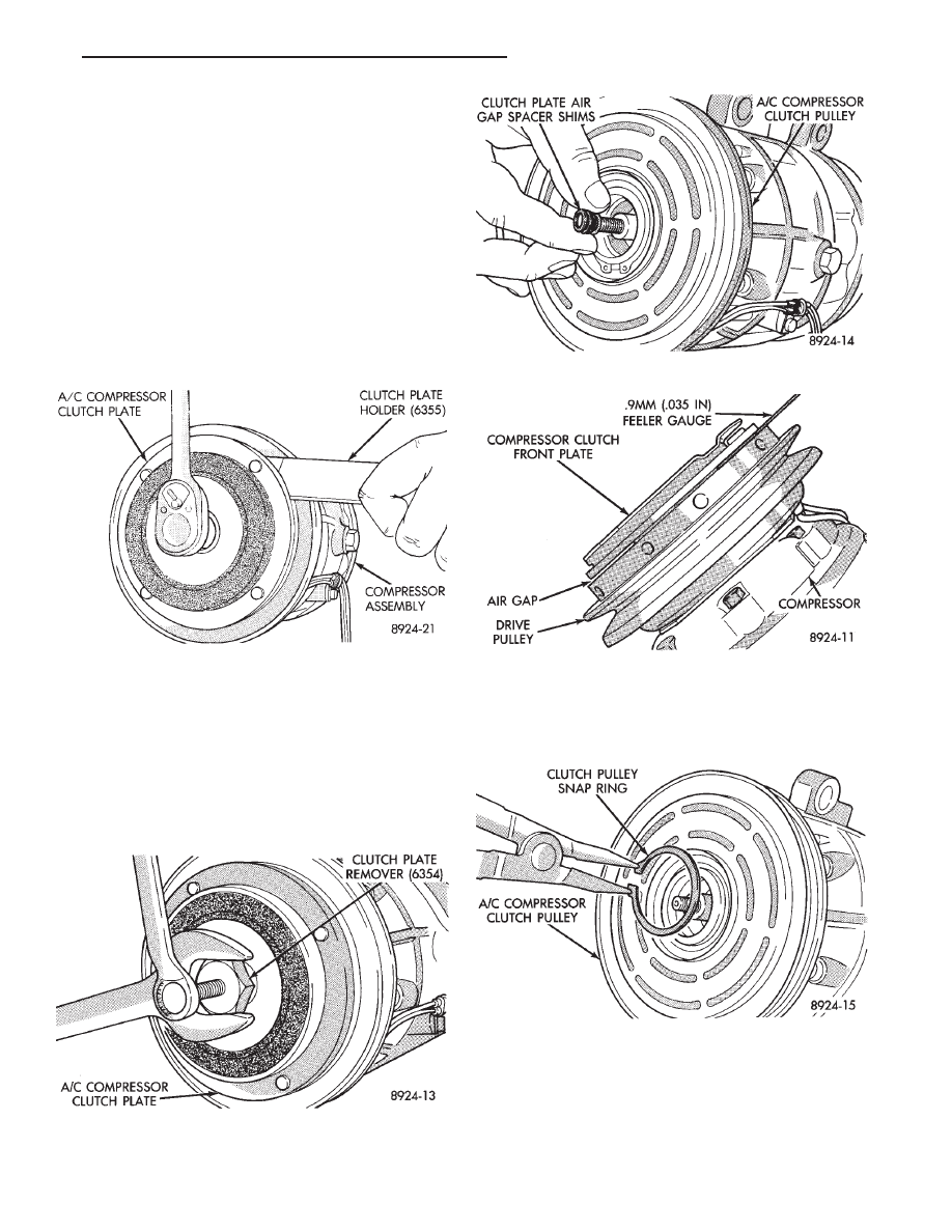
(1) Remove clutch retaining center nut by using
Clutch Plate Holder (6355) (Fig. 4).
(2) Using a Clutch Plate Remover (6354), remove
the clutch front plate from the compressor (Fig. 5).
When installing the front plate, select the proper
shims to achieve .5 to .9 mm (.020 to .035 inch) air
gap to the pulley surface (Fig. 6). To install front
plate, align shaft key to groove in front plate hub.
Push on until it seats, and measure the air gap (Fig.
7).
(3) Remove clutch pulley retaining snap ring (Fig.
7) and pull the pulley from the assembly (Fig. 8).
(4) Remove the clutch coil wire lead strap screw.
(5) Remove clutch coil retaining snap ring (Fig. 10)
and pull the coil from the assembly (Fig. 11). When
installing the clutch coil, align the pin on the front of
Fig. 4 Remove or Install Front Plate Retaining Nut
Fig. 5 Remove Front Plate
Fig. 6 Install Front Plate and Shims
Fig. 7 Measure Front Plate Air Gap
Fig. 8 Remove or Install Pulley Snap Ring
Ä
HEATING AND AIR CONDITIONING
24 - 19
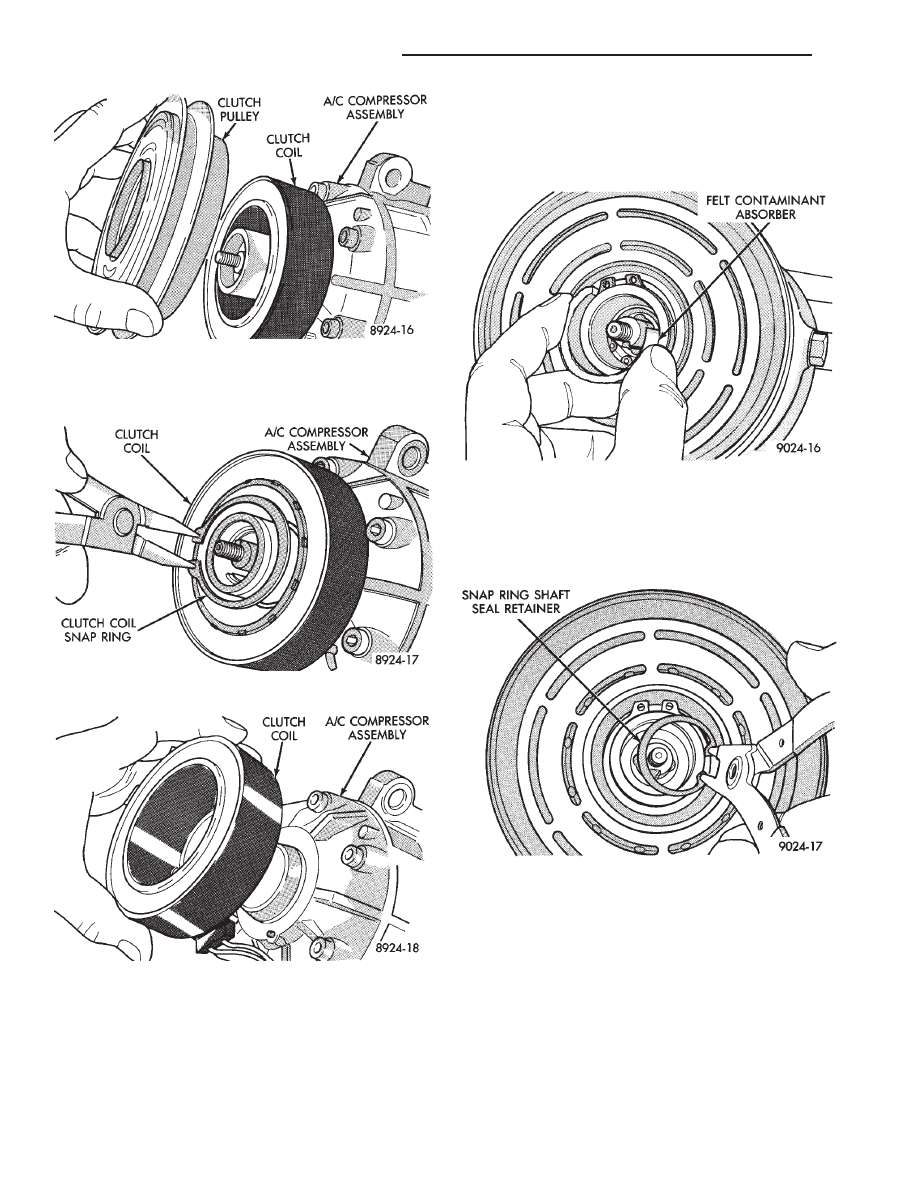
the compressor to the middle hole in the hub of the
coil. Position the pin in the snap ring gap.
To install, reverse the preceding operation.
COMPRESSOR FRONT SHAFT SEAL
REMOVAL
(1) Using a refrigerant recovery machine, remove
the refrigerant from the A/C system.
(2) Remove A/C compressor.
(3) Remove the compressor clutch assembly and
shaft key.
(4) Remove the felt contaminant absorber and re-
tainer (Fig. 1).
(5) Using a mineral spirits based solvent, thor-
oughly clean and dry the seal end of the compressor.
(6) Remove the snap ring shaft seal retainer (Fig.
2). Do not use the old snap ring to assemble.
(7) Using Seal Remover/Installer (6429), remove
the shaft seal (Fig. 3).
INSTALLATION
(1) Lubricate the new shaft seal with refrigerant
oil.
(2) Place Seal Protector (6231) over the end of com-
pressor shaft (Fig. 4). Use the larger flat end of the
remover/installer to push the seal in until it seats.
The snap ring groove should be visible above the seal
(Fig. 5).
(3) Install clutch/coil assembly.
(4) Install compressor.
Fig. 9 Remove or Install Pulley
Fig. 10 Remove or Install Clutch Coil Snap Ring
Fig. 11 Remove or Install Clutch Coil
Fig. 1 Felt Contaminant Absorber
Fig. 2 Shaft Seal Snap Ring
24 - 20
HEATING AND AIR CONDITIONING
Ä
Нет комментариевНе стесняйтесь поделиться с нами вашим ценным мнением.
Текст