Chrysler Le Baron, Dodge Dynasty, Plymouth Acclaim. Manual — part 190
(5) Evacuate and charge the refrigerant system. If
oil loss of 3 ml (1 oz) or greater is suspected, refer to
Oil Level in the Refrigerant Service Procedures sec-
tion.
COMPRESSOR HIGH PRESSURE CUT-OUT SWITCH
The High Pressure Cut Out (HPCO) switch is lo-
cated on the rear cover of the Variable Displacement
Compressor (Fig. 6). The function of the switch is to
disengage the compressor clutch by monitoring the
compressor discharge (high) pressure. The HPCO
Switch is in the same circuit as the Differential Pres-
sure Cut Out (DPCO) switch and Ambient Switch.
DIAGNOSIS
Review Safety Precautions and Warnings before
proceeding with this operation.
Connect a suitable manifold gauge set to the refrig-
erant system service ports. Work area temperature
can not be below 21°C (70°F).
(1) Raise hood of vehicle.
(2) With gear selector in park or neutral, and park
brake set, start engine and allow to idle at 1300 rpm.
(3) Set the A/C controls to A/C and High blower.
(6) If the high pressure gauge reads below 2963
kPa (430 psi)
6138 kPa (20 psi) the compressor
clutch should be engaged.
CAUTION: Do not allow engine to overheat when ra-
diator air flow is blocked.
(7) Block radiator air flow with a suitable cover to
increase the high side pressure to at least 3100 kPa
(450 psi). Compressor clutch should disengage.
(8) Remove cover from front of vehicle to allow
high side pressure to decrease. When pressure drops
below 1826 kPa (265 psi), compressor clutch should
engage.
REMOVAL AND INSTALLATION
(1) Using a refrigerant recovery machine, remove
the refrigerant from the A/C system.
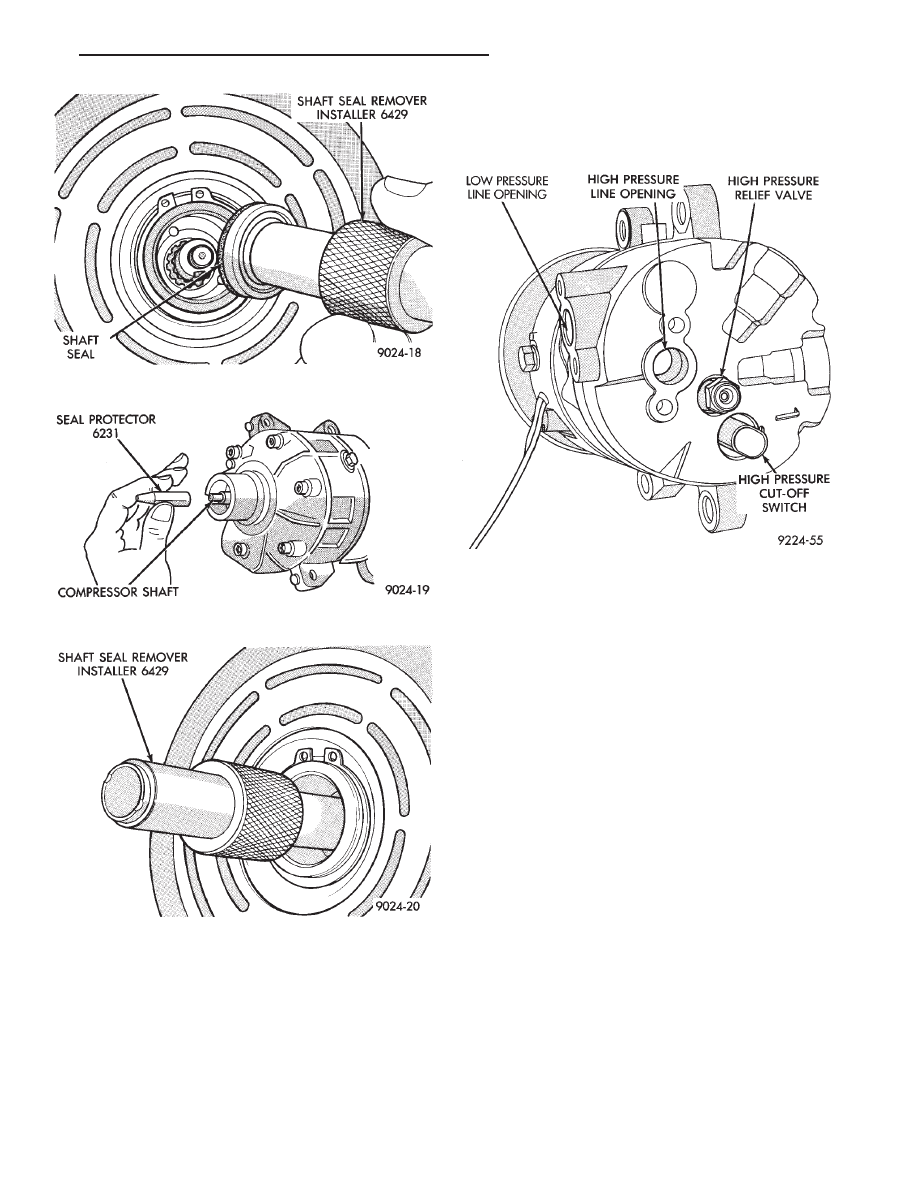
Fig. 3 Remove Shaft Seal
Fig. 4 Shaft Seal Protector
Fig. 5 Install Shaft Seal
Fig. 6 Variable Displacement Compressor—Model
6C17
Ä
HEATING AND AIR CONDITIONING
24 - 21
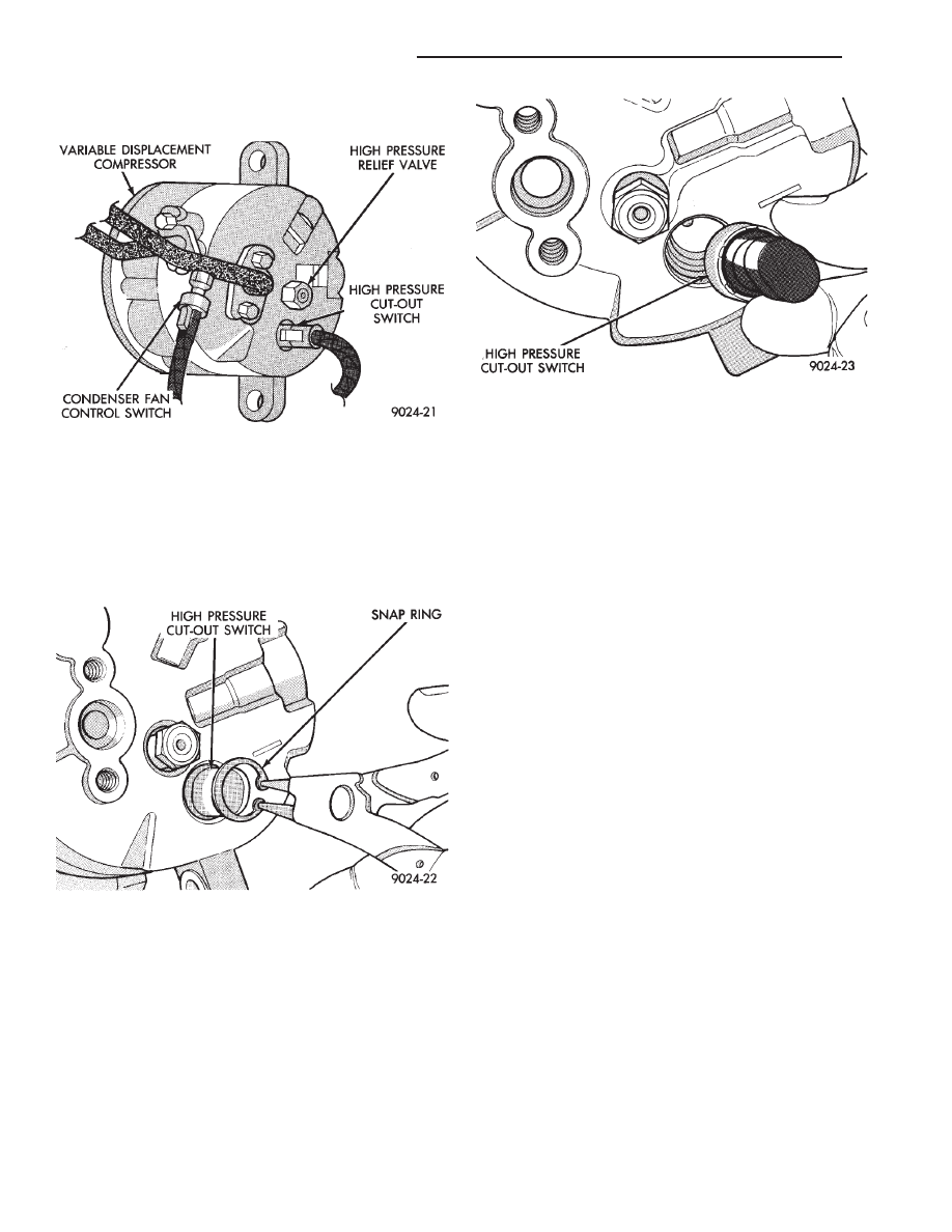
(2) Disconnect wire connector from the high pres-
sure cut-out switch (Fig. 7).
(3) Remove snap ring securing the switch in the
compressor end cover (Fig. 8).
CAUTION: The high pressure cut-out switch service
kit has two snap rings. One is black and the other
is silver. Use the one which has the same color as
the original one in the compressor.
(4) Pull switch straight out from end cover. Re-
move and discard used O-ring seal (Fig. 9).
To install, reverse the preceding operation using a
new O-ring seal. Evacuate and charge the refrigerant
system.
COMPRESSOR HIGH PRESSURE RELIEF VALVE
(HPR)
DIAGNOSIS
The High Pressure Relief valve prevents damage to
the air conditioning system if excessive pressure de-
velops. Excessive pressure may be caused by con-
denser air flow blockage, refrigerant overcharge, or
air and moisture in the system.
The High Pressure Relief valve vents only a small
amount of refrigerant necessary to reduce system
pressure and then reseats itself. The majority of the
refrigerant is conserved in the system. The valve is
calibrated to vent at a pressure of 3100 to 4140 Kpa
(450 to 600 psi). If a valve has vented a small
amount of refrigerant, it does not necessarily mean
the valve is defective.
VALVE LOCATION
The High Pressure Relief Valve is located on the
compressor end plate.
REMOVAL AND INSTALLATION
(1) Using a refrigerant recovery machine, remove
the refrigerant from the A/C system.
(2) Rotate the high pressure relief valve counter-
clockwise and separate relief valve from the vehicle
(Fig. 10).
To install, reverse the preceding operation using a
new O-ring seal. Evacuate and charge the refrigerant
system.
COMPRESSOR MAIN OR SUB CONTROL VALVES
If the main or sub control valve is leaking refrig-
erant to the atmosphere, replace the main or sub
control valve. If a functional problem is suspected
with the main or sub control valve, the compressor
should be replaced.
REMOVAL AND INSTALLATION
(1) Using a refrigerant recovery machine, remove
the refrigerant from the A/C system.
(2) Remove the compressor assembly. Position it to
gain access to the control valves. It is not necessary
to disconnect the suction or discharge lines from the
compressor.
Fig. 7 High Pressure Cut-out Switch
Fig. 8 Remove or Install Snap Ring
Fig. 9 Remove or Install High Pressure Cut-out
Switch
24 - 22
HEATING AND AIR CONDITIONING
Ä

(3) Remove the snap ring retaining either the
main or sub control valve to the compressor (Fig. 11).
(4) Pull the main or sub control valve from the
compressor end cover (Fig. 12).
To install, reverse the preceding operation using
new O-ring seals. Evacuate and charge the refriger-
ant system.
Fig. 10 High Pressure Relief Valve Removal
Fig. 11 Main or Sub Control Valve Snap Ring
Fig. 12 Remove or Install Main or Sub Control Valve
Ä
HEATING AND AIR CONDITIONING
24 - 23
FIXED DISPLACEMENT COMPRESSOR—MODEL 10PA17
INDEX
page
page
Compressor
. . . . . . . . . . . . . . . . . . . . . . . . . . . . . 24
Compressor Clutch/Coil Assembly
. . . . . . . . . . . . 24
Compressor Front Shaft Seal
. . . . . . . . . . . . . . . 27
Compressor High-Pressure Relief Valve
. . . . . . . 30
Refrigerant System Diagnosis
. . . . . . . . . . . . . . . 30
COMPRESSOR
COMPRESSOR NOISE
Excessive noise that occurs when the air condition-
ing is being used, can be caused by:
• Loose bolts
• Mounting brackets
• Loose clutch
• Excessive high refrigerant system operating pres-
sure
Verify compressor drive belt condition, proper re-
frigerant charge and head pressure before compressor
repair is performed.
For noise diagnostic procedures, refer to the Com-
pressor Noise and Compressor Clutch Diagnosis
chart in this section.
REMOVAL AND INSTALLATION
The A/C compressor may be removed and posi-
tioned without discharging the refrigerant system.
Discharging is not necessary if removing the A/C
compressor clutch/coil assembly, engine, cylinder
head, or generator.
WARNING: REFRIGERANT PRESSURES REMAIN
HIGH
EVEN
THOUGH
THE
ENGINE
MAY
BE
TURNED
OFF.
BEFORE
REMOVING
A
FULLY
CHARGED COMPRESSOR, REVIEW THE SAFETY
PRECAUTIONS AND WARNINGS SECTION IN THIS
GROUP. DO NOT TWIST OR KINK THE REFRIGER-
ANT LINES WHEN REMOVING A FULLY CHARGED
COMPRESSOR.
SAFETY
GLASSES
MUST
BE
WORN.
(1) Disconnect Negative battery cable.
(2) Loosen and remove drive belts (refer to Group
7, Cooling System) and disconnect compressor clutch
wire lead.
(3) Remove refrigerant lines from compressor (if
necessary).
(4) Remove compressor attaching nuts and bolts.
(5) Remove compressor. If refrigerant lines were
not removed, lift compressor/clutch assembly and tie
it to a suitable component.
To install, reverse the preceding operation. If nec-
essary, refer to Charging Refrigerant System in the
Refrigerant Service Procedures section.
COMPRESSOR CLUTCH/COIL ASSEMBLY
CLUTCH INOPERATIVE
The air conditioning compressor clutch electrical
circuit is controlled by the engine controller. The
controller is located in the engine compartment out-
board of the battery.
If the compressor clutch does not engage:
Verify refrigerant charge.
If the compressor clutch still does not engage check
for battery voltage at the low pressure or differential
pressure cut-off switch located on the expansion
valve. If voltage is not detected, refer to:
• Group 8W, Wiring Diagrams.
• The appropriate Powertrain Diagnostic Procedures
Manual for diagnostic information.
If voltage is detected at the cut-off switch, recon-
nect switch. Then check for battery voltage between
the compressor clutch connector terminals.
If voltage is detected, perform A/C Clutch Coil
Tests.
CLUTCH COIL TESTS
(1) Verify battery state of charge. (Test indicator
in battery should be green).
(2) Connect an ammeter (0-10 ampere scale) in se-
ries with the clutch coil terminal. Use a volt meter
(0-20 volt scale) with clip leads measuring voltage
across the battery and A/C clutch.
(3) With A/C control in A/C mode and blower at
low speed, start the engine and run at normal idle.
(4) The A/C clutch should engage immediately and
the clutch voltage should be within two volts of the
battery voltage. If the A/C clutch does not engage,
test the fusible link.
(5) The A/C clutch coil is acceptable if the current
draw is 2.0 to 3.7 amperes at 11.5-12.5 volts at clutch
coil. This is with the work area temperature at 21°C
(70°F). If voltage is more than 12.5 volts, add electri-
cal loads by turning on electrical accessories until
voltage reads below 12.5 volts.
If coil current reads zero, the coil is open and
should be replaced. If the ammeter reading is 4 am-
peres or more, the coil is shorted and should be re-
placed. If the coil voltage is not within two volts of
the battery voltage, test clutch coil feed circuit for
excessive voltage drop.
24 - 24
HEATING AND AIR CONDITIONING
Ä
Нет комментариевНе стесняйтесь поделиться с нами вашим ценным мнением.
Текст