Chrysler Le Baron, Dodge Dynasty, Plymouth Acclaim. Manual — part 97

SERVICE PROCEDURES
CONTROL MODULE (ASCM)
REMOVAL
(1) Disconnect negative battery cable.
(2) Remove right side trunk trim panel.
(3) Remove electrical connectors from control mod-
ule and relay (Fig. 11).
(4) Remove control module mounting screws and
remove assembly.
INSTALLATION
(1) Install relay on the control module mounting
bracket (if required).
(2) Place control module in mounting position.
(3) Install mounting screws and tighten to 2-3 N
Im
(19-29 in. lbs.) torque.
(4) Install control module and relay wiring connec-
tors (Fig. 11).
(5) Install right side trunk trim panel.
(6) Connect negative battery cable.
COMPRESSOR RELAY
REMOVAL
(1) Remove right side trunk trim panel.
(2) Remove electrical connector from relay.
(3) Remove relay from control module mounting
bracket by prying out on locating clip (Fig. 11)
INSTALLATION
(1) Push relay onto bracket (relay will Lock into
position.)
(2) Install electrical connector.
(3) Install trim panel.
COMPRESSOR ASSEMBLY
REMOVAL
(1) Disconnect battery negative cable.
(2) Raise vehicle, see Hoisting, Group 0.
(3) Remove cover from compressor assembly. Re-
move air hose (see AIR LINES) and electrical connec-
tors (Fig. 12)
(4) Remove compressor assembly mounting screws
and lower assembly from vehicle.
(5) Remove mounting bracket screws and slide
mounting bracket away from compressor.
INSTALLATION
(1) Slide mounting bracket on compressor and in-
stall screws and tighten to 8 N
Im (70 in. lbs.) torque.
DO NOT OVER TORQUE THESE SCREWS.
(2) Install compressor assembly to frame rail and
tighten screws to 8 N
Im (70 in. lbs.) torque. DO NOT
OVER TORQUE THESE SCREWS.
(3) Connect air hose and electrical connector to com-
pressor assembly.
(4) Install cover on compressor assembly and tighten
screws to 6 N
Im (40 in. lbs.) torque.
(5) Lower vehicle and connect battery negative
cable.
(6) Check operation of the system.
AIR DRYER
REMOVAL
Remove compressor assembly. See COMPRESSOR
ASSEMBLY.
Fig. 11 Control Module and Relay Wiring
Fig. 12 Compressor Assembly
Ä
SUSPENSION AND DRIVESHAFTS
2 - 85
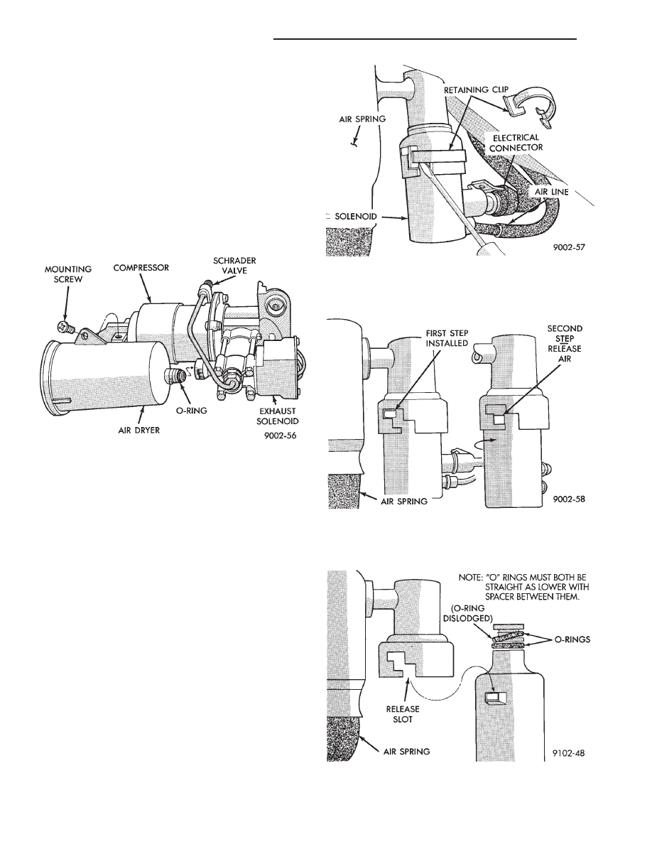
(1) Remove dryer-to-compressor retaining screw
(Fig. 13).
(2) Rotate dryer assembly 90° to release retaining
tangs from exhaust solenoid housing and withdraw
unit.
INSTALLATION
Inspect O-Ring for damage and location on dryer
assembly.
(1) Insert and index air dryer locking tangs into
exhaust solenoid outlet.
(2) Rotate air dryer assembly to lock position and
install air dryer-to-compressor retaining screw (Fig.
13).
SOLENOIDS (STRUTS AND AIR SPRINGS)
Front struts and rear springs are equipped with so-
lenoids that control air pressure and volume within
the assemblies. The solenoids are electrically oper-
ated to allow air input, contain air, or release air
pressure, depending on control module commands.
REMOVAL
WARNING: DO NOT ATTEMPT TO REMOVE OR IN-
STALL
SOLENOIDS
WHILE
AIR
SUSPENSION
(FRONT STRUTS AND REAR AIR SPRINGS) ARE
SUPPORTING VEHICLE.
Disconnect negative battery cable. Raise vehicle
and remove wheel and tire assembly then remove so-
lenoid(s) as follows:
(1) Separate electrical connection to solenoid.
(2) Disconnect air line, see Air Lines and Fittings.
Solenoids have molded square tangs to fit into
stepped notches of the air spring housing. The
notches provide an air relief position and a retaining
position. The retaining position is locked with a re-
taining clip.
(3) Remove retaining clip (Fig. 14).
(4) Rotate solenoid to first step in housing and al-
low air pressure to vent (Fig. 15).
(5) Rotate solenoid to release slot and remove (Fig.
16).
Fig. 13 Air Dryer Remove/Install
Fig. 14 Remove Retaining Clips
Fig. 15 Release Air Pressure
Fig. 16 Remove Solenoid (Inspect O Ring)
2 - 86
SUSPENSION AND DRIVESHAFTS
Ä

INSTALL
(1) Inspect O-Ring condition and position on sole-
noid stem. (O-Ring can become dislodged during re-
moval (Fig. 16).
(2) Install solenoid with tangs to top ledge of hous-
ing and install retaining clip.
(3) Reconnect air line and electrical connection.
STRUT (AIR SUSPENSION) DAMPER
ASSEMBLY
Service procedures for removal and installation for
(air or steel spring) assemblies are essentially the
same. Except for air venting/recharging and discon-
necting/connecting air lines and electrical connection.
REMOVAL
(1) Disconnect battery negative cable.
(2) Hoist vehicle and remove wheel and tire assem-
bly.
(3) See AIR LINES AND FITTINGS and discon-
nect air line.
(4) Disconnect electrical leads, solenoid and height
sensors.
(5) See SOLENOIDS (STRUT AND AIR SPRING)
and vent air spring and remove solenoids.
(6) See STRUT DAMPER ASSEMBLY in FRONT
SUSPENSION and remove strut.
DISASSEMBLY/ASSEMBLE
Disassembly is restricted to upper mount and bear-
ing housing. The strut shock absorber, air spring
with integral height sensor, solenoid and wiring har-
ness are serviced as an assembly.
(1) Hold retaining plate locking washer and re-
move strut rod nut.
(2) Remove locking washer, retainer plate, spacer,
flat washer and mount/bearing housing assembly
(Fig. 17).
(3) Assemble in reverse order. Hold retainer plate
locking washer with suitable tool and tighten strut
rod nut to 75 N
Im (55 ft. lbs.) torque.
INSTALLATION
(1) See STRUT DAMPER ASSEMBLY in FRONT
SUSPENSION and install strut.
(2) Install solenoid, see: SOLENOIDS (STRUT
AND AIR SPRINGS).
(3) Connect electrical leads, solenoid and height
sensor.
(4) Charge (inflate) air spring. See RECHARGE-
AIR SPRING to activate spring solenoid and air com-
pressor. Add air for 60 seconds.
RECHARGE AIR SPRING
To activate compressor; Ground Pin S08 to Pin
X20.
To Activate Spring Solenoid:
• LF: Ground Pin S31 to X20
• RF: Ground Pin S30 to X20
• RR: Ground Pin S32 to X20
AIR SPRINGS REAR
REMOVAL
(1) Disconnect battery negative cable, hoist vehicle
and remove wheel and tire assembly.
(2) See AIR LINES AND FITTINGS and discon-
nect air line and electrical connector from solenoid.
(3) See SOLENOIDS (STRUT AND AIR SPRINGS)
and vent air from spring. Remove solenoid.
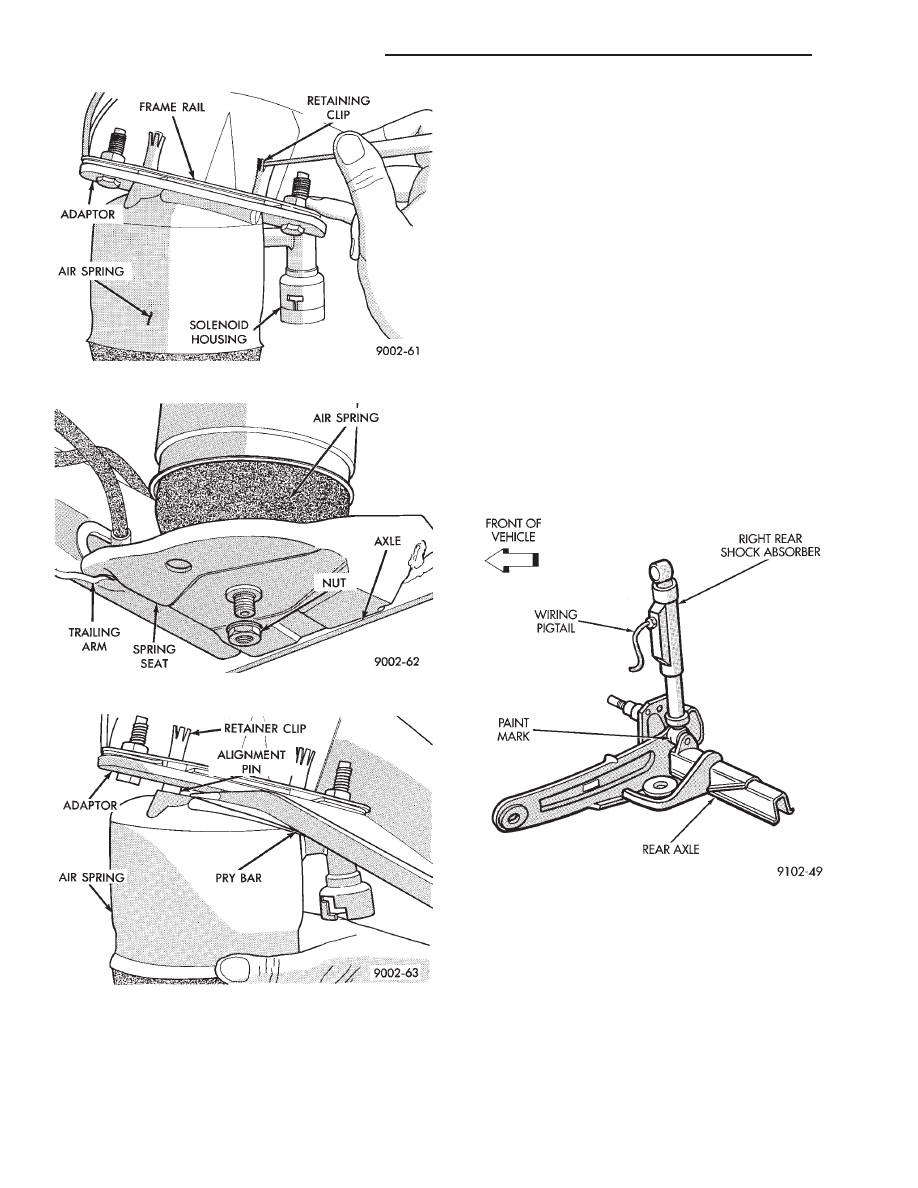
(4) Release upper air spring alignment/retainer
clips. (Fig. 18)
(5) Remove lower spring to axle nut (Fig. 19).
(6) Pry assembly down to pull alignment studs
through retaining clips (Fig. 20). Remove assembly.
INSTALLATION
(1) Position assembly lower stud into axle seat and
upper alignment pins through frame rail adaptor.
(2) Install upper retaining clips.
(3) Install lower spring to axle nut: LOOSE AS-
SEMBLE.
(4) Install solenoid and connect air line and electri-
cal connector.
(5) Charge (inflate) air spring. See RECHARGING
AIR SPRING and add air for 60 seconds.
(6) AFTER partial air recharge tighten lower nut
Fig. 17 Air Strut Upper Mount Assembly
Ä
SUSPENSION AND DRIVESHAFTS
2 - 87
to 68 N
Im (50 ft. lbs.) torque.
(7) Install wheel and tire assembly. Lower vehicle,
install wheel and tire assembly and connect battery
negative cable.
RIGHT SHOCK ABSORBER (WITH HEIGHT
SENSOR)
REMOVAL
(1) Disconnect battery negative cable.
(2) Raise vehicle, see Hoisting, Group 0.
(3) Remove tire assembly.
(4) Disconnect height sensor connector located on
right rear frame rail.
(5) Remove shock, see Shock Absorbers, Removal.
INSTALLATION
(1) Install shock assembly, see Shock Absorbers,
Installation.
(2) Route height sensor wire through retaining
clips and then tie strap to fuel filler tube.
(3) Snap height sensor connector into underbody
harness connector.
(4) Install wheel/tire assembly.
(5) Height sensor wiring harness and white paint
mark on bottom shock eye must face to the front of
the vehicle (Fig. 21).
Fig. 18 Release Retaining Clips
Fig. 19 Remove/Install Lower Spring to Axle Nut
Fig. 20 Pry Assembly Out of Retaining Clips
Fig. 21 Right Rear Shock Absorber Installation
2 - 88
SUSPENSION AND DRIVESHAFTS
Ä
Нет комментариевНе стесняйтесь поделиться с нами вашим ценным мнением.
Текст