Chrysler Le Baron, Dodge Dynasty, Plymouth Acclaim. Manual — part 71
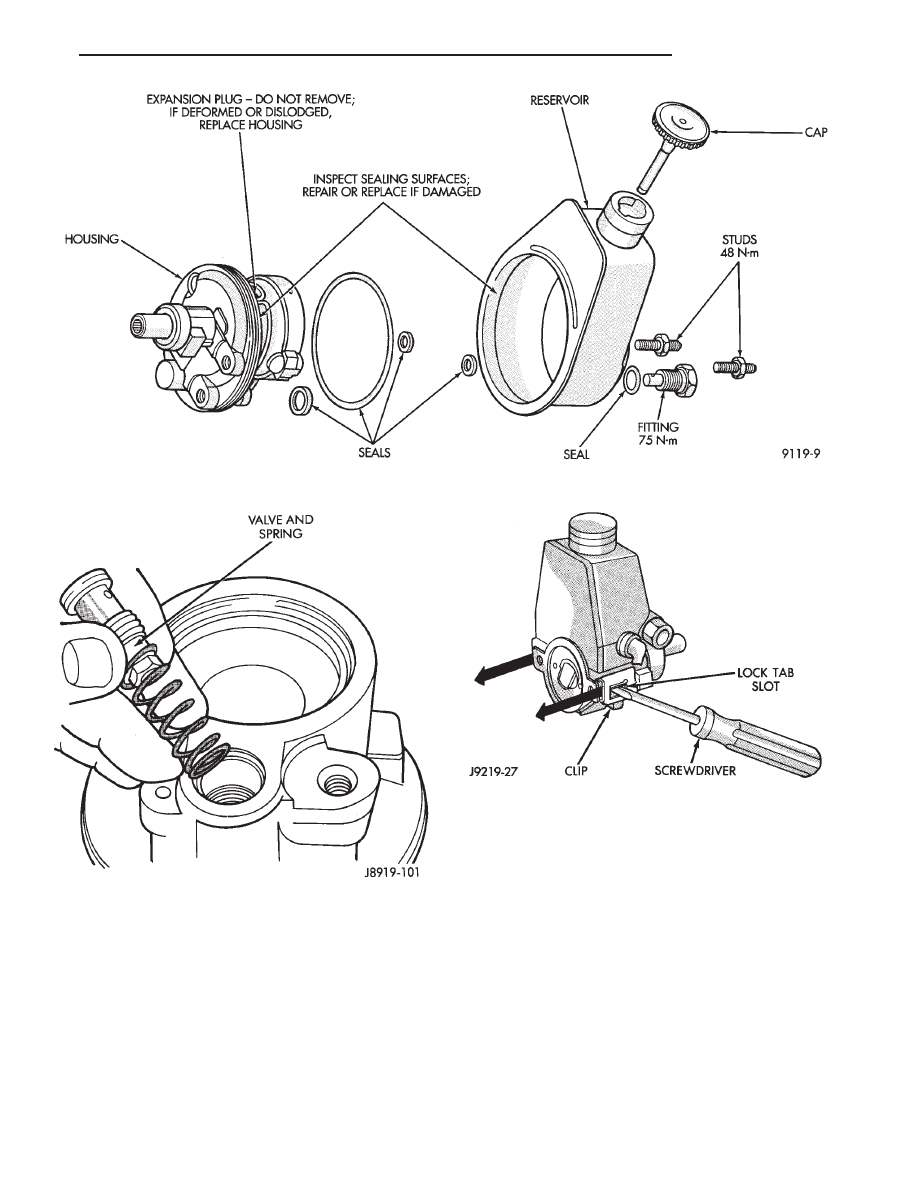
(4) Slide and tap in reservoir retainer clips until
tab locks to housing (Fig. 4).
(5) Install
pump.
Refill
reservoir
with
Mopar
Power Steering Fluid or equivalent.
FLOW CONTROL VALVE FITTING O-RING SEAL
REMOVAL
(1) Remove pressure hose from pump fitting. Re-
move pump and pulley if necessary.
(2) Remove fitting from pump housing (Fig. 5). Pre-
vent flow control valve and spring from sliding
out of housing bore.
(3) Remove and discard O-ring seal (Fig. 5).
INSTALLATION
(1) If necessary, clean and install flow control valve
and spring in pump housing bore (Fig. 5). Be sure the
hex nut end of the valve is facing the in toward
the pump.
(2) Install O-ring seal onto fitting (Fig. 5).
(3) Install fitting in pump housing and tighten to 75
N
Im (55 ft. lbs.)
(4) Install pump and pulley if necessary. Install
pressure hose to fitting.
Fig. 1 Pump and Reservoir
Fig. 2 Flow Control Valve/Spring Installation
Fig. 3 Remove Reservoir Clips (Typical)
Ä
STEERING
19 - 23

POWER STEERING PUMP—INITIAL OPERATION
CAUTION: The fluid level should be checked with
engine off to prevent injury from moving compo-
nents. Use only Mopar
T
Power Steering Fluid. Do
not use automatic transmission fluid. Do not over-
fill.
Wipe filler cap clean, then check the fluid level.
The dipstick should indicate FULL COLD when the
fluid is at normal temperature of approximately 21°C
to 27°C (70°F to 80°F).
(1) Fill power steering pump fluid reservoir to the
proper level.
(2) Start the engine and let run for a few seconds.
Then turn the
engine off.
(3) Add fluid if necessary. Repeat the above proce-
dure until the fluid level remains constant after run-
ning the engine.
(4) Raise front wheels of vehicle off the ground.
(5) Start the engine. Slowly turn the steering
wheel right and left, lightly contacting the wheel
stops. Then turn the engine off.
(6) Add power steering fluid if necessary.
(7) Lower the vehicle and turn the steering wheel
slowly from lock to lock.
(8) Stop the engine. Check the fluid level and refill
as required.
(9) If the fluid is extremely foamy, allow the vehi-
cle to stand a few minutes and repeat the above pro-
cedure.
Fig. 4 Remove Reservoir (Typical)
Fig. 5 Flow Control Valve Fitting
Removal/Installation
19 - 24
STEERING
Ä

POWER STEERING GEAR
INDEX
page
page
General Information
. . . . . . . . . . . . . . . . . . . . . . . 25
Outer Tie Rod
. . . . . . . . . . . . . . . . . . . . . . . . . . . 27
Steering Gear Service
. . . . . . . . . . . . . . . . . . . . . 25
GENERAL INFORMATION
The power steering gear (Fig. 1) should NOT be
serviced or adjusted. If a malfunction or oil leak
occurs. The complete steering gear should be
replaced.
If a steering gear boot needs to be replaced due to
damage, refer to the power steering gear service sec-
tion in this manual for proper procedure.
The power steering system consists of these four
major components. Power Steering Gear, Power Steer-
ing Pump, Pressure Hose, and Return Line. Turning of
the steering wheel is converted into linear travel
through the meshing of the helical pinion teeth with
the rack teeth. Power assist steering is provided by an
open center, rotary type control valve which directs oil
from the pump to either side of the integral rack piston.
Road feel is controlled by the diameter of a torsion
bar which initially steers the vehicle. As required
steering effort increases, as in a turn. The torsion bar
twists, causing relative rotary motion between the
rotary valve body and the valve spool. This movement
directs oil behind the integral rack piston, which, in
turn, builds up hydraulic pressure and assists in the
turning effort.
The drive tangs on the pinion of the power steering
pump mate loosely with a stub shaft. This is to permit
manual steering control to be maintained if the drive
belt on the power steering pump should break. How-
ever, under these conditions, steering effort will be
increased.
STEERING GEAR SERVICE
The power steering gear should NOT be ser-
viced or adjusted. If a malfunction or oil leak
occurs. The complete steering gear should be
replaced.
REMOVAL
(1) Raise vehicle See Hoisting, Group 0. Put oil drain
pan under vehicle to catch power steering fluid.
(2) Remove front road wheels.
(3) Remove both tie rod ends from steering knuckles,
using Puller Special Tool C-3894-A (Fig. 1).
(4) Disconnect engine damper strut from crossmem-
ber (if so equipped).
(5) Remove the 3 front suspension crossmember at-
taching bolts and the nut (Fig. 2) from the locating
stud. Lower front suspension crossmember, using
Fig. 1 Power Steering Gear Assembly
Ä
STEERING
19 - 25

transmission jack, so that the steering gear can be
disconnected from the steering column.
(6) Remove fluid tubes (Fig. 3) from the power
steering pump to the steering gear. See hose removal
procedure.
(7) Remove the 4 bolts (Fig. 3) attaching steering
gear to front suspension crossmember.
(8) Remove steering gear assembly from crossmem-
ber.
INSTALLATION
An assistant will be required in the vehicle, at
the time of steering gear replacement. To help
guide the steering column coupling onto the
steering gear assembly.
(1) Install steering gear assembly on the front cross-
member. Install the 4 steering gear to front crossmem-
ber mounting bolts (Fig. 3).
(2) Using a transmission jack raise the front cross-
member and steering gear against the frame rails.
Install the 3 crossmember to frame rail attaching
Fig. 2 Crossmember Remove/Replace
Fig. 3 Steering Gear And Crossmember
Fig. 1 Tie Rod End Removal
19 - 26
STEERING
Ä
Нет комментариевНе стесняйтесь поделиться с нами вашим ценным мнением.
Текст