Chrysler Le Baron, Dodge Dynasty, Plymouth Acclaim. Manual — part 256
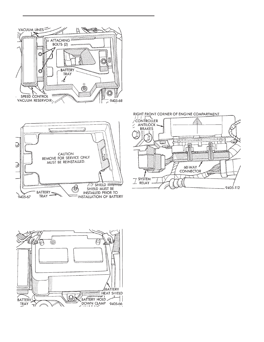
(10) Install battery on battery tray and install and
securely tighten the battery hold down clamp (Fig.
13). Then install heat shield, on battery (Fig. 13).
(11) Install battery cables on battery. Securely
tighten clamping bolts on battery cable terminals.
(12) Reset any electrical components of the vehicle
which were affected by the removal of the battery.
(13) Road test vehicle to verify correct operation of
the vehicles’s base and Antilock brake systems.
ELECTRONIC COMPONENTS
CONTROLLER ANTILOCK BRAKE CAB
REMOVE
(1) Turn vehicle ignition off.
(2) Disconnect the wiring harness connector from
the Antilock system relay (Fig. 1). Relay will be re-
moved as part of the CAB bracket.
CAUTION: BEFORE REMOVING 60 WAY CONNEC-
TOR FROM THE CAB VERIFY THAT THE VEHICLE’S
IGNITION IS IN THE OFF OR LOCK POSITION. IF IG-
NITION IS ON WHEN 60 WAY CONNECTOR IS RE-
MOVED
FROM
THE
CAB
DAMAGE
TO
THE
CONTROLLER COULD OCCUR.
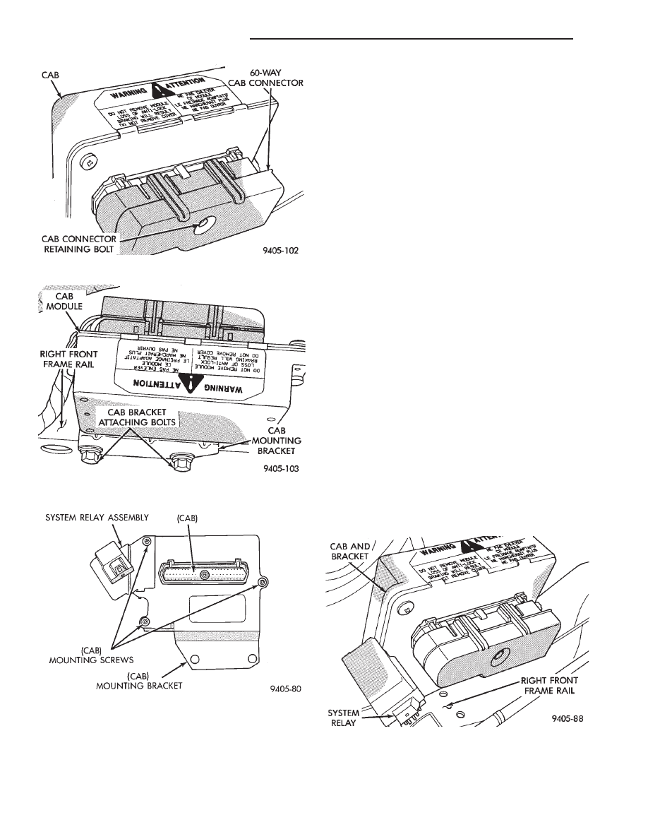
(3) Loosen bolt (Fig. 2) retaining the wiring har-
ness 60 way connector to the CAB. Then disconnect
the 60 way connector (Fig. 2) from the CAB by pull-
ing it straight out, do not twist connector when re-
moving.
(4) Remove the 2 bolts (Fig. 3) attaching the CAB
module mounting bracket, to the frame rail of the ve-
hicle.
(5) Remove the CAB and its mounting bracket as
an assembly from the vehicle from the vehicle.
(6) Remove the 3 screws (Fig. 4) attaching the
CAB to the CAB mounting bracket. Then separate
CAB from mounting bracket.
Fig. 11 Vacuum Reservoir Installation And
Attaching Bolts
Fig. 12 Battery Tray Access Shield Installed
Fig. 13 Battery Hold Down Clamp And Heat Shield
Installed
Fig. 1 CAB Location
Ä
ANTILOCK 4 BRAKE SYSTEM
5 - 41
INSTALL
(1) Install CAB and system relay/bracket assembly
on CAB mounting bracket (Fig. 4). Install the 3 CAB
to CAB mounting bracket attaching screws (Fig. 4).
Torque the 3 CAB to mounting bracket attaching
screws to 12 N
Im (106 in. lbs.).
(2) Install the CAB, system relay and mounting
bracket on the frame rail of the vehicle. Install the 2
bolts (Fig. 3) attaching the CAB mounting bracket to
the frame rail of the vehicle. Torque the 2 CAB mount-
ing bracket attaching bolts (Fig. 3) to 28 N
Im (250 in.
lbs.).
CAUTION: BEFORE INSTALLING 60 WAY CONNEC-
TOR ON THE CAB VERIFY THAT THE VEHICLE’S
IGNITION IS IN THE OFF OR LOCK POSITION. IF
IGNITION IS ON WHEN 60 WAY CONNECTOR IS
INSTALLED ON THE CAB, DAMAGE TO THE CON-
TROLLER COULD OCCUR.
(3) Install the wiring harness 60 way connector (Fig.
2) into the CAB electrical connector as far as possible
by hand. After 60 way connector is installed as far as
possible by hand, use the 60 way connector retaining
bolt (Fig. 2) to fully seat connector into the CAB. Then
torque the wiring harness 60 way CAB connector
retaining bolt to 4 N
Im (38 in. lbs.).
(4) Install the wiring harness connector onto the
Antilock system relay (Fig. 1). Be sure locking tab
on wiring harness connector is fully engaged
with lock on system relay.
(5) Road test vehicle to verify correct operation of the
vehicles’s Antilock brake system.
REMOVAL/INSTALLATION OF SYSTEM RELAY
The antilock brake system, system relay is serviced
as an assembly, with the mounting bracket. The sys-
tem relay is mounted to a separate bracket which is
attached to the CAB and mounting bracket assembly
(Fig. 5).
Fig. 2 CAB 60 Way Connector And Retaining Bolt
Fig. 3 CAB Bracket To Frame Rail Mounting Bolts
Fig. 4 CAB Removal From Mounting Bracket
Fig. 5 Antilock Brakes System Relay Location
5 - 42
ANTILOCK 4 BRAKE SYSTEM
Ä
REMOVE
(1) Hold system relay with one hand, while pulling
strait down on the wiring harness connector. Until
connector is free from the relay (do not twist the
connector).
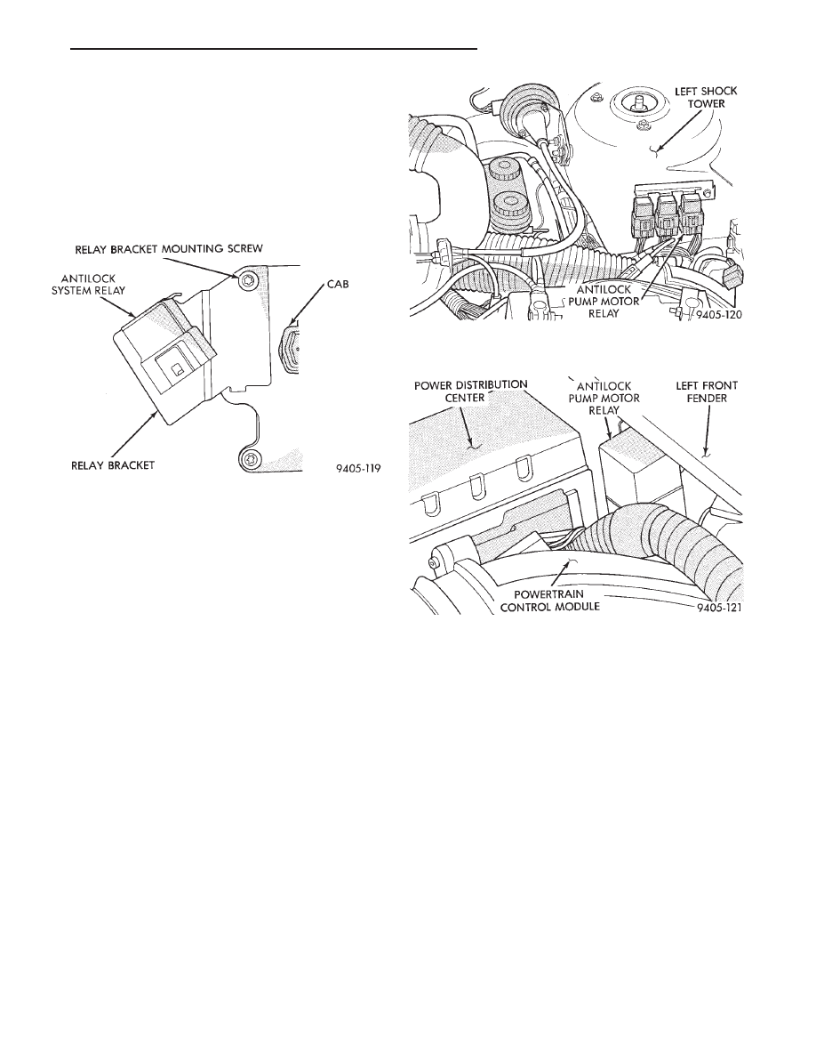
(2) Remove screw (Fig. 6) holding the system relay
and bracket to the CAB bracket. Then remove the
system relay and mounting bracket assembly from
the CAB bracket.
INSTALL
(1) Mount the system relay and its mounting
bracket assembly to the CAB mounting bracket, with
the mounting screw (Fig. 6).
(2) Holding the system relay with one hand, push-
ing the wiring harness connector strait onto the ter-
minals of the relay. Make sure connector is fully
seated onto terminals of the system relay and the
lock on the wiring harness connector is fully engaged
with the relay.
(3) Road test vehicle to verify correct operation of
the vehicles’s Antilock brake system.
REMOVE/INSTALL PUMP MOTOR RELAY
Find location of Antilock Pump Motor Relay (Fig. 7
& 8), depending on whether the vehicle being ser-
viced has or does not have a power distribution cen-
ter PDC.
(1) Hold the Antilock pump motor relay with one
hand, while pulling wiring harness relay connector
strait off the relay terminals.
(2) Remove the pump motor relay assembly from
the vehicle.
(3) Installation is done in the reverse order off re-
moval. Be sure that the wiring harness connector is
fully seated onto the terminals of the Pump Motor
Relay.
WHEEL SPEED SENSORS
INSPECTION
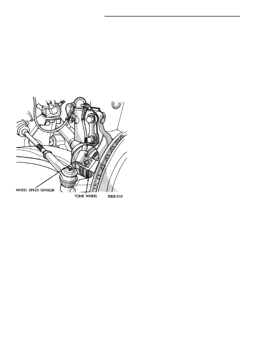
Inspect tonewheel for missing or broken teeth, this
can cause erratic sensor signals.
Tonewheel should show no evidence of contact with
the wheel speed sensor. If contact was made, deter-
mine cause and correct.
Excessive runout of the tonewheel can cause er-
ratic wheel speed sensor. Replace assembly if runout
exceeds approximately 0.25 mm (0.010 inch).
FRONT WHEEL SPEED SENSOR (FIG. 9)
REMOVAL
(1) Raise vehicle and remove wheel and tire as-
sembly.
(2) Remove screw from grommet retainer clip that
holds the grommet into fender shield (Fig. 9).
(3) Remove the 2 screws that fasten the sensor
routing tube to the frame rail.
Fig. 6 System Relay And Bracket Removal
Fig. 7 Pump Motor Relay Location On AA Body W/O
Power Distribution Center
Fig. 8 Pump Motor Relay Location On AJ Body With
Power Distribution Center
Ä
ANTILOCK 4 BRAKE SYSTEM
5 - 43
(4) Carefully, pull sensor assembly grommet from
fender shield.
(5) Unplug speed sensor connector from vehicle
wiring harness.
(6) Remove the sensor assembly grommets from
the retainer brackets.
(7) Remove sensor head screw.
(8) Carefully, remove sensor head from steering
knuckle. If the sensor has seized, due to corrosion,
DO NOT USE PLIERS ON SENSOR HEAD. Use
a hammer and a punch and tap edge of sensor ear,
rocking the sensor side to side until free.
INSTALLATION
(1) Connect the wheel speed sensor connector to
the wiring harness.
(2) Push sensor assembly grommet into hole in
fender shield. Install clip and screw.
(3) Install the 2 screws that fasten the speed sen-
sor routing tube to the frame rail.
(4) Install sensor grommets in brackets on fender
shield and strut damper.
(5) Coat the speed sensor with High Temperature
Multi-purpose E.P. Grease before installing into the
steering knuckle. Install screw tighten to 7 N
Im (60
in. lbs.)
CAUTION: Proper installation of wheel speed sen-
sor cables is critical to continued system operation.
Be sure that cables are installed in retainers. Fail-
ure to install cables in retainers, as shown in this
section, may result in contact with moving parts
and/or over extension of cables, resulting in an
open circuit.
REAR WHEEL SPEED SENSOR (FIGS. 10 AND
11)
REMOVAL
(1) Raise vehicle and remove wheel and tire as-
sembly.
(2) Remove sensor assembly grommet from under-
body and pull harness through hole in underbody.
(3) Unplug connector from harness.
(4) Remove
sensor
assembly
grommets
from
bracket which is screwed into the body hose bracket,
just forward of trailing arm bushing (batwing brack-
et.)
(5) Remove sensor and brake tube assembly clip,
located on the inboard side of trailing arm.
(6) Remove sensor wire fastener from rear brake
hose bracket.
(7) Remove outboard sensor assembly retainer nut.
This nut also is used to capture the brake tube clip.
(8) Remove sensor head screw.
(9) Carefully, remove sensor head from adapter as-
sembly. If the sensor has seized, due to corrosion, DO
NOT USE PLIERS ON SENSOR HEAD. Use a ham-
mer and a punch and tap edge of sensor ear, rocking
the sensor side to side until free.
INSTALLATION
Installation is reverse order of removal. Be sure to
coat sensor with High Temperature Multi-purpose
E.P. Grease before installing into adapter assembly.
Tighten screw to 7 N
Im (60 in. lbs.) torque.
Fig. 9 Front Wheel Speed Sensor Routing
5 - 44
ANTILOCK 4 BRAKE SYSTEM
Ä
Нет комментариевНе стесняйтесь поделиться с нами вашим ценным мнением.
Текст