Chrysler Le Baron, Dodge Dynasty, Plymouth Acclaim. Manual — part 257
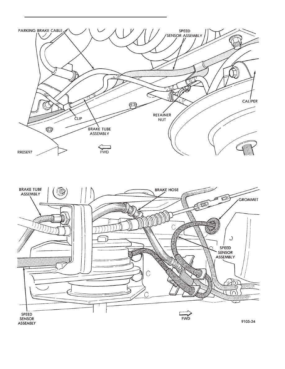
Fig. 11 Body Routing of Rear Speed Sensor Wiring
Fig. 10 Rear Wheel Speed Sensor Routing at Trailing Arm
Ä
ANTILOCK 4 BRAKE SYSTEM
5 - 45
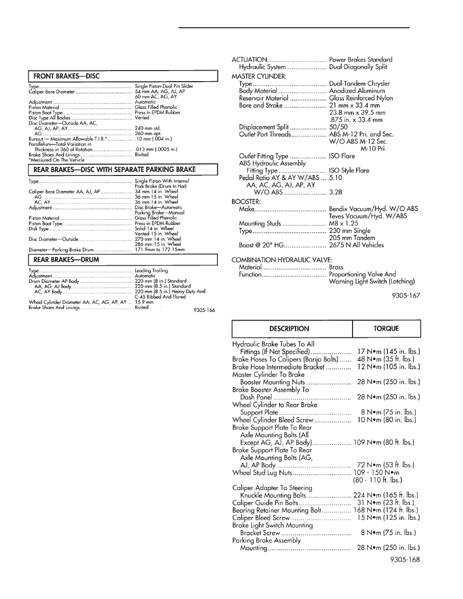
SPECIFICATIONS
SPECIFICATIONS METRIC
BRAKE ACTUATION SYSTEM
TIGHTENING REFERENCE
5 - 46
ANTILOCK 4 BRAKE SYSTEM
Ä
MANUAL TRANSAXLE CLUTCH
CONTENTS
page
page
CLEANING PRECAUTIONS
. . . . . . . . . . . . . . . . . 6
CLUTCH CABLE MECHANISM
. . . . . . . . . . . . . . 1
CLUTCH CABLE REPLACEMENT
. . . . . . . . . . . . 2
CLUTCH CHATTER COMPLAINTS
. . . . . . . . . . . 1
CLUTCH DISC REPLACEMENT
. . . . . . . . . . . . . 5
CLUTCH PEDAL NOISE/POP
. . . . . . . . . . . . . . . 2
CLUTCH PEDAL POSITION SWITCH
. . . . . . . . . 4
EXCESSIVE CLUTCH SPIN TIME/CLASH
INTO REVERSE COMPLAINTS
. . . . . . . . . . . . 1
GENERAL INFORMATION . . . . . . . . . . . . . . . . . . 1
RELEASE BEARING AND FORK . . . . . . . . . . . . . 6
GENERAL INFORMATION
Throughout this group, references may be made to
a particular vehicle by letter or number designation.
A chart showing the breakdown of these designations
is included in the Introduction Section at the front of
this service manual.
The clutch used in all models are a single, dry disc
type with no adjustment for wear being provided in
the clutch itself.
The clutch pedal is connected to the release shaft
through a cable and lever.
The upper end of the clutch pedal pivots in the
pedal bracket on two nylon bushings. These bushings
do not require periodic lubrication.
CLUTCH CHATTER COMPLAINTS
For all clutch chatter complaints, do the following:
(1) Check for loose, misaligned, or broken engine
and transmission mounts. If present, they should be
corrected at this time. Test vehicle for chatter. If
chatter is gone, there is no need to go any further. If
chatter persists:
(2) Check to see if clutch cable routing is correct
and operates smoothly.
(3) Check for loose connections in drive train. Cor-
rect any problems and determine if clutch chatter
complaints has been satisfied. If not,
(4) Remove transaxle. See Group 21, Manual Tran-
saxle, for procedure.
(5) Check to see if the release bearing is sticky or
binding. Replace bearing, if needed.
(6) Check linkage for excessive wear on bushings.
Replace all worn parts. A small amount of bearing
grease between the release shaft bushings and the
shaft is beneficial, but not required.
(7) Check flywheel and clutch pressure plate for
contamination (dirt, oil) or scored. Replace flywheel
and/or pressure plate, if required.
(8) Check to see if the clutch disc hub splines are
damaged. Replace with new disc.
(9) Check input shaft splines for damage. Replace
if necessary.
(10) Check for uneven wear on clutch fingers.
EXCESSIVE CLUTCH SPIN TIME/CLASH INTO
REVERSE COMPLAINTS
For all excessive clutch spin time/clash into reverse
complaints, do the following:
(1) Depress clutch pedal to floor and hold. After
three seconds, shift to reverse. If clash is present,
clutch has excessive spin time.
(2) Remove transaxle. See Group 21, Manual Tran-
saxle, for procedure.
(3) Check the input shaft spline, clutch disc splines
and release bearing for dry rust. If present, clean
rust off and apply a light coat of bearing grease to
the input shaft splines. Apply grease on the input
shaft splines only where the clutch disc slides.
(4) Check to see if the clutch disc hub splines are
damaged, replace with new disc if required.
(5) Check the input shaft for damaged splines. Re-
place as necessary.
(6) Check for excessive clutch disc runout or
warpage.
(7) Install clutch assembly and transaxle.
CLUTCH CABLE MECHANISM
The manual transaxle clutch release system has a
unique self-adjusting mechanism to compensate for
clutch disc wear. This adjuster mechanism is located
within the clutch pedal. The preload spring main-
tains tension on the cable. This tension keeps the
clutch release bearing continuously loaded against
the fingers of the clutch cover assembly.
When the pedal is depressed, teeth on the adjuster
and the positioner engage and pull the release cable.
A spring located behind the adjuster ensures proper
tooth engagement.
When the pedal is released, the adjuster contacts
the bumper. This separates the adjuster and posi-
tioner teeth, allowing the preload spring to function.
Ä
MANUAL TRANSAXLE CLUTCH
6 - 1
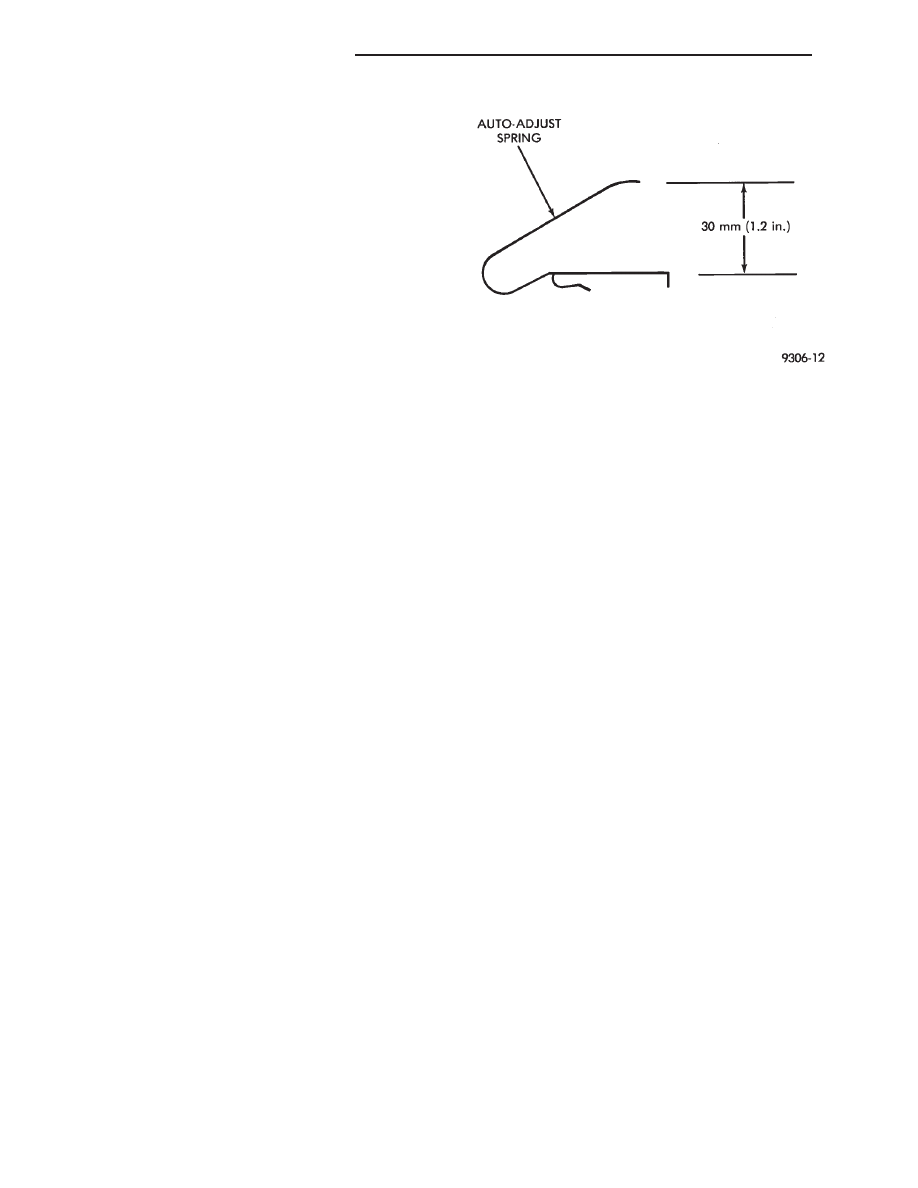
CLUTCH PEDAL NOISE/POP
The mechanism which automatically adjusts the
clutch cable to compensate for clutch wear may emit
a loud clicking or pop noise under certain circum-
stances.
The cause of this noise in most cases is the clutch
cable auto-adjust spring being below design load
specifications. The condition can be corrected by ei-
ther bending the auto-adjust spring to bring it back
to specifications or replacing the spring (Fig. 1).
The auto-adjust spring is located on the back of the
clutch pedal.
CLUTCH CABLE REPLACEMENT
(1) Remove retainer from clutch release lever at
transaxle by pulling on the tail of the ball stud (Fig.
2).
(2) Pry out ball end of cable from positioner ad-
juster and remove cable, passing it through the hoop
in the shock tower mounting bracket.
(3) Inspect cable for wear and contamination. The
inner cable strand should move smoothly inside the
cable housing. If cable is worn or damaged, replace
the cable. Do not lubricate.
(4) Inspect the clutch pedal and adjuster mecha-
nism for wear. Apply a multipurpose lubricant on
parts indicated (Fig. 2).
(5) To
install,
reverse
procedure
of
steps
(3)
through (1).
(6) After installation, push and lift the clutch
pedal 2 or 3 times to allow adjuster mechanism to
function.
(7) Check clutch pedal position switch operation.
Fig. 1 Clutch Cable Auto-Adjust Spring
6 - 2
MANUAL TRANSAXLE CLUTCH
Ä
Нет комментариевНе стесняйтесь поделиться с нами вашим ценным мнением.
Текст