Chrysler Le Baron, Dodge Dynasty, Plymouth Acclaim. Manual — part 272
GENERATOR TEST PROCEDURES ON VEHICLE
INDEX
page
page
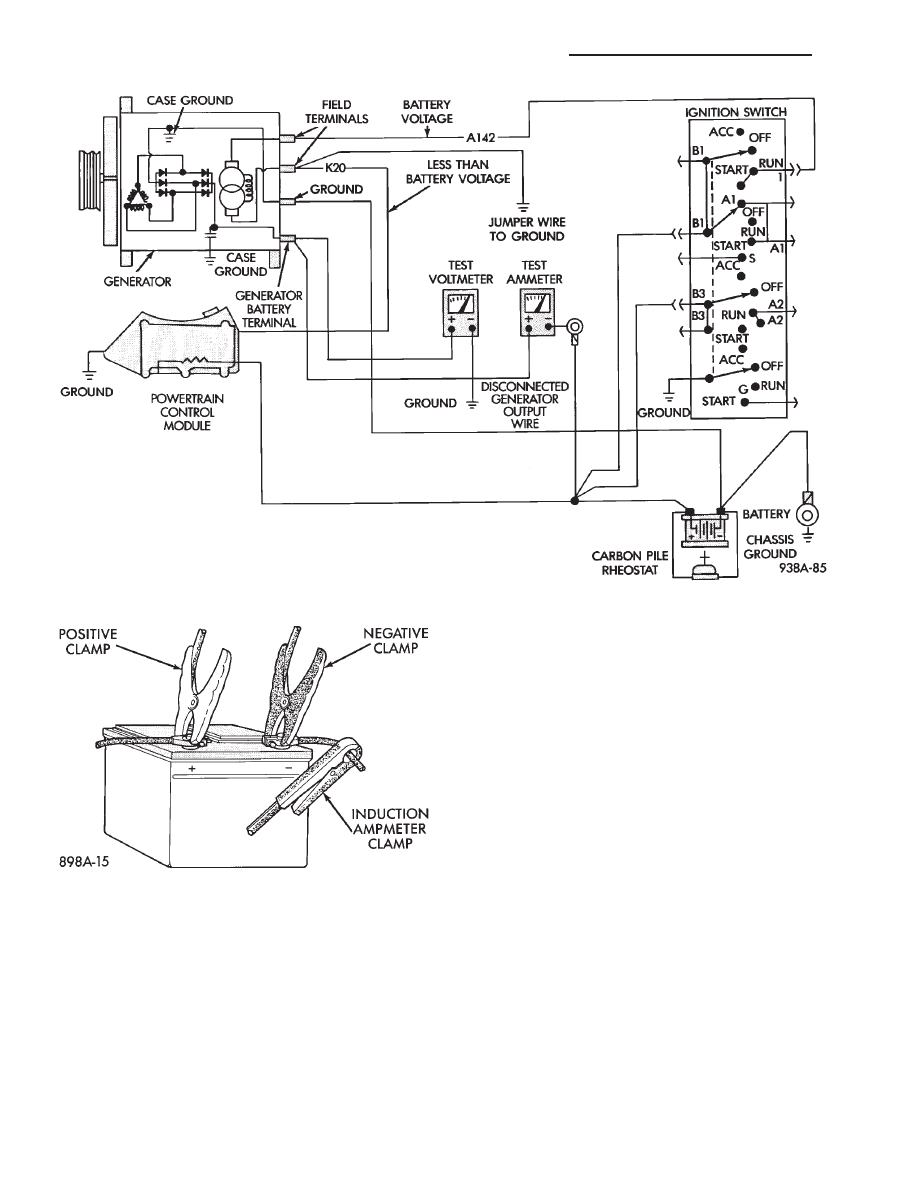
Charging System Diagnostics (Fig. 1)
. . . . . . . . . 19
Current Output Test
. . . . . . . . . . . . . . . . . . . . . . 19
Output Wire Resistance Test
. . . . . . . . . . . . . . . . 19
CHARGING SYSTEM DIAGNOSTICS (Fig. 1)
OUTPUT WIRE RESISTANCE TEST
The generator output wire resistance test shows
the amount of voltage drop across the generator out-
put wire between the generator B+ terminal and the
positive battery post.
PREPARATION
Before starting test, make sure the vehicle has a
fully charged battery. Tests and procedures to check
for a fully charged battery is shown in the Battery
section.
(1) Turn the ignition switch OFF.
(2) Disconnect battery NEGATIVE cable.
(3) Disconnect the generator B+ output wire from
the generator output battery terminal (Fig. 2).
(4) Connect a 0-150 ampere scale (DC) ammeter in
series between B+ terminal and output wire (Fig. 2
and 3). Connect positive lead to B+ terminal, and
negative lead to output wire.
(5) Using o-18 volt scale voltmeter, connect the
positive lead to the disconnected (B+) output wire
(Fig. 2). Connect the negative lead to positive battery
post.
(6) Remove fresh air hose between Powertrain
Control Module and air cleaner if necessary.
(7) Connect jumper wire between a good ground
and K20 circuit terminal at the back of the genera-
tor.
CAUTION: Do not connect the A142 circuit terminal
(Fig. 2) to ground the Fusible link will burn.
(8) Connect an engine tachometer and connect bat-
tery negative cable.
(10) Connect a volt/amp tester equipped with a
variable carbon pile rheostat between battery termi-
nals (Fig. 4).
Caution: Be sure the carbon pile is in OFF position
before connecting leads.
TEST
(1) Start engine. Immediately after starting, re-
duce engine speed to idle.
(2) Adjust engine speed and carbon pile to main-
tain 20 amperes flowing in the circuit. Observe volt-
meter reading. Voltmeter reading should not exceed
0.5 volts.
RESULTS
If a higher voltage drop is shown, inspect, clean
and tighten all connections between generator B+
terminal and battery positive post. A voltage drop
test may be performed at each connection to locate a
connection with excessive resistance. If resistance
tests are satisfactory, reduce engine speed, turn off
carbon pile, and turn off ignition switch.
(1) Disconnect battery negative cable.
(2) Remove test ammeter, voltmeter, carbon pile,
and tachometer.
(3) Remove jumper wire.
(4) Connect generator output wire to generator B+
terminal.
(5) Connect battery negative cable.
(6) Connect fresh air hose between Powertrain
Control Module and air cleaner if removed.
CURRENT OUTPUT TEST
The current output test decides whether the gener-
ator can deliver its rated current output. For gener-
ator
identification
and
output
amperage
specifications, refer to Generator Specifications.
For generator maximum voltage at individual tem-
peratures, refer to Generator Output Voltage Specifi-
cations.
PREPARATION
Before starting any tests, make sure the vehicle
has a fully charged battery. Tests and procedures to
check for a fully charged battery is shown in Battery
section.
(1) Disconnect battery negative cable.
(2) Disconnect output wire at the B+ terminal
(Figs. 2 and 5).
(3) Connect a 0-150 ampere scale (DC) ammeter in
series between the B+ terminal and output wire.
Connect Positive lead to B+ terminal and negative
lead to output wire.
(4) Using 0-18 voltmeter, connect positive lead to
B+ terminal (Figs. 2 and 5). Connect negative lead
to a good ground.
Ä
BATTERY/STARTING/CHARGING SYSTEMS DIAGNOSTICS
8A - 19

Fig. 1 Charging Diagnostics
8A - 20
BATTERY/STARTING/CHARGING SYSTEMS DIAGNOSTICS
Ä

(5) Connect an engine tachometer and connect bat-
tery negative cable.
(6) Connect a volt/amp tester equipped with a vari-
able carbon pile rheostat between battery terminals
(Fig. 6). Be sure carbon pile is in OFF position before
connecting leads.
(7) Remove fresh air hose between Powertrain
Control Module computer and air cleaner if neces-
sary.
(8) Full field the generator. Connect a jumper wire
between a good ground and K20 circuit terminal at
the back of the generator (Figs. 2 and 5).
CAUTION: Do not connect the A142 circuit terminal
(Fig. 2) to ground. Fusible link will burn.
TEST
(1) Start the engine. Immediately after starting,
reduce engine speed to idle.
Fig. 2 Generator Wiring Connections
Fig. 3 Generator Output Wire Resistance Test
Fig. 4 Volt/Amp Tester Connections
Ä
BATTERY/STARTING/CHARGING SYSTEMS DIAGNOSTICS
8A - 21
(2) Adjust the carbon pile and engine speed in
steps until an engine speed of 1250 rpm, and a volt-
meter reading of 15 volts is obtained.
CAUTION: Do not allow the battery voltage to ex-
ceed 16 volts.
(3) The generator amperage must meet the output
requirements for the particular generator being
tested. Refer to Generator Specifications for genera-
tor identification and amperage outputs.
RESULTS
(1) If amperage reading is less than specified, and
generator output wire resistance is not found exces-
sive from the previous tests, generator should be re-
placed. Refer to Group 8B, Battery/Starter/Generator
Service, Generator Replacement. These generators
are not intended to be disassembled for service. It
must be replaced as an assembly.
(2) After current output test is completed, reduce
engine speed, turn off carbon pile, and turn off igni-
tion switch.
(3) Disconnect battery negative cable.
(4) Remove test ammeter, voltmeter, tachometer
and carbon pile.
(5) Remove jumper wire between K20 circuit ter-
minal and ground.
(6) Connect output wire to B+ terminal.
(7) Connect negative battery cable.
(8) Connect fresh air hose between powertrain con-
trol module and air cleaner if removed.
Fig. 5 Generator Current Output Test
Fig. 6 Volt/Amp Tester Connections
8A - 22
BATTERY/STARTING/CHARGING SYSTEMS DIAGNOSTICS
Ä
Нет комментариевНе стесняйтесь поделиться с нами вашим ценным мнением.
Текст