Chrysler Le Baron, Dodge Dynasty, Plymouth Acclaim. Manual — part 27
Various sensors provide the inputs necessary for
the PCM to correctly regulate fuel flow at the fuel
injector. These include the manifold absolute pres-
sure, throttle position, oxygen sensor, coolant tem-
perature, and vehicle speed sensors. In addition to
the sensors, various switches and relays provide im-
portant information and system control. The inputs
include the park/neutral switch and air conditioning
clutch switch. The outputs include the auto shutdown
relay and fuel pump relay.
All inputs to the PCM are converted into signals.
Based on these inputs the PCM adjusts air-fuel ratio,
ignition timing and other controlled outputs. The
PCM adjusts the air-fuel ratio by changing the injec-
tor pulse width. Injector pulse width is the period of
time the injector is energized.
SYSTEM DIAGNOSIS
The PCM tests many of its own input and output
circuits. If a fault is found in a major system, the in-
formation is stored in memory. Technicians can dis-
play fault information through the instrument panel
Malfunction Indicator lamp (instrument panel Check
Engine lamp) or by connecting the DRBII scan tool.
For diagnostic trouble code information, refer to On
Board Diagnostics in 2.2L/2.5L Single Point Fuel In-
jection—General Diagnosis section of this group.
CCD BUS
Various modules exchange information through a
communications port called the CCD Bus. The pow-
ertrain control module (PCM) transmits vehicle load
data on the CCD Bus.
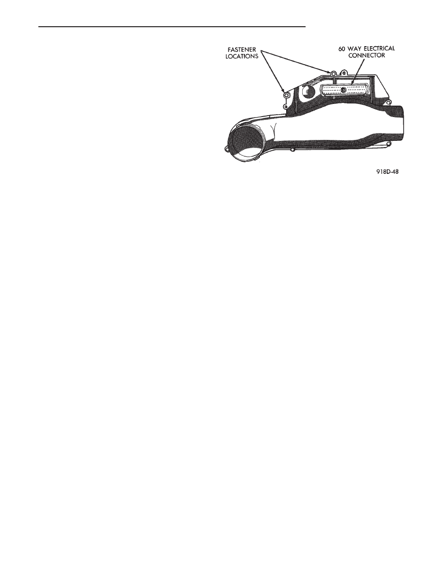
POWERTRAIN CONTROL MODULE
The powertrain control module (PCM) is a digital
computer containing a microprocessor (Fig. 2). The
PCM receives input signals from various switches
and sensors that are referred to as PCM Inputs.
Based on these inputs, the PCM adjusts various en-
gine and vehicle operations through devices that are
referred to as PCM Outputs.
PCM Inputs:
• Air Conditioning Controls
• Battery Voltage
• Brake Switch
• Coolant Temperature Sensor
• Distributor (Hall Effect) Pick-up
• Manifold Absolute Pressure (MAP) Sensor
• Oxygen Sensor
• SCI Receive
• Speed Control System Controls
• Throttle Position Sensor
• Park/Neutral Switch (automatic transaxle)
• Vehicle Speed Sensor
PCM Outputs:
• Air Conditioning Clutch Relay
• Generator Field
• Idle Air Control Motor
• Auto Shutdown (ASD) Relay
• Canister Purge Solenoid
• Malfunction Indicator (Check Engine) Lamp
• Data Link Connector (Diagnostic Connector)
• Electronic EGR Transducer
• Fuel Injector
• Ignition Coil
• Part Throttle Unlock Solenoid (Automatic Tran-
saxle)
• Radiator Fan Relay
• Speed Control Solenoids
• Tachometer Output
Based on inputs it receives, the PCM adjusts fuel
injector pulse width, idle speed, ignition spark ad-
vance, ignition coil dwell and canister purge opera-
tion. The PCM regulates operation of the EGR,
cooling fan, A/C and speed control systems. The PCM
changes generator charge rate by adjusting the gen-
erator field.
The PCM adjusts injector pulse width (air-fuel ra-
tio) based on the following inputs.
• battery voltage
• coolant temperature
• exhaust gas content
• engine speed (distributor pick-up)
• manifold absolute pressure
• throttle position
The PCM adjusts ignition timing based on the fol-
lowing inputs.
• coolant temperature
• engine speed (distributor pick-up)
• manifold absolute pressure
• throttle position
The Auto Shutdown (ASD) and Fuel Pump relays
are mounted externally, but turned on and off by the
PCM through the same circuit.
The distributor pick-up signal is sent to the PCM.
If the PCM does not receive a distributor signal
within approximately one second of engine cranking,
Fig. 2 PCM
Ä
FUEL SYSTEMS
14 - 25
it de-activates the ASD relay and fuel pump relay.
When these relays are deactivated, power is shut off
from the fuel injector, fuel pump, ignition coil, and
oxygen sensor heater element.
The
PCM
contains
a
voltage
converter
that
changes battery voltage to a regulated 8.0 volts to
power the distributor pick-up and vehicle speed sen-
sor. The PCM also provides a 5.0 volts supply for the
coolant temperature sensor, manifold absolute pres-
sure sensor and throttle position sensor.
AIR CONDITIONING SWITCH SENSE—PCM INPUT
ALL VEHICLES EXCEPT AC-BODY
When the air conditioning or defrost switch is put
in the ON position and the low pressure and high
pressure switches are closed, the PCM receives an in-
put indicating that the air conditioning has been se-
lected. After receiving this input, the PCM activates
the A/C compressor clutch by grounding the A/C
clutch relay. The PCM also adjusts idle speed to a
scheduled RPM to compensate for increased engine
load.
AC-BODY VEHICLES
When the air conditioning or defrost switch is put
in the ON position and the low pressure switch, high
pressure switch and electronic cycling switch close,
the PCM receives an air conditioning select input.
After receiving this input, the PCM activates the
A/C compressor clutch by grounding the A/C com-
pressor clutch relay. The PCM also adjusts idle speed
to a scheduled RPM to compensate for increased en-
gine load.
BATTERY VOLTAGE—PCM INPUT
The PCM monitors the battery voltage input to de-
termine fuel injector pulse width and generator field
control. If battery voltage is low, the PCM increases
injector pulse width.
BRAKE SWITCH—PCM INPUT
When the brake switch is activated, the PCM re-
ceives an input indicating that the brakes are being
applied. After receiving the input, the PCM vents the
speed control servo. Venting the servo turns the
speed control system off.
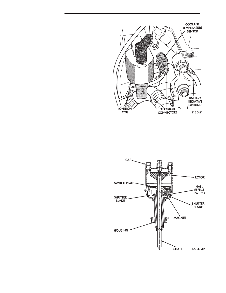
COOLANT TEMPERATURE SENSOR—PCM INPUT
The coolant temperature sensor is installed behind
the thermostat housing and ignition coil in the hot
box. The sensor provides an input voltage to the
PCM (Fig. 3). As coolant temperature varies, the sen-
sors resistance changes, resulting in a different input
voltage to the PCM.
The PCM demands slightly richer air-fuel mixtures
and higher idle speeds until the engine reaches nor-
mal operating temperature.
This sensor is also used for cooling fan control.
DISTRIBUTOR (HALL EFFECT) PICK-UP—PCM
INPUT
The distributor pick-up supplies engine speed to
the PCM. The distributor pick-up is a Hall Effect de-
vice (Fig. 4).
A shutter (sometimes referred to as an interrupter)
is attached to the distributor shaft. The shutter con-
tains four blades, one per engine cylinder. A switch
plate is mounted to the distributor housing above the
Fig. 3 Coolant Temperature Sensor
Fig. 4 Distributor Pick-Up—Typical
14 - 26
FUEL SYSTEMS
Ä

shutter. The switch plate contains the distributor
pick-up which is a Hall Effect device and magnet.
The shutter blades rotate through the distributor
pick-up. As the shutter blades pass through the pick-
up, they interrupt the magnetic field. The Hall effect
device in the pick-up senses the change in the mag-
netic field and switches on and off (which creates
pulses), generating the input signal to the PCM. The
PCM calculates engine speed through the number of
pulses generated.
MANIFOLD ABSOLUTE PRESSURE (MAP)
SENSOR—PCM INPUT
The PCM supplies 5 volts to the MAP sensor. The
MAP sensor converts intake manifold pressure into
voltage. The PCM monitors the MAP sensor output
voltage. As vacuum increases, MAP sensor voltage
decreases proportionately. Also, as vacuum decreases,
MAP sensor voltage increases proportionately.
During cranking, before the engine starts running,
the PCM determines atmospheric air pressure from
the MAP sensor voltage. While the engine operates,
the PCM determines intake manifold pressure from
the MAP sensor voltage.
Based on MAP sensor voltage and inputs from
other sensors, the PCM adjusts spark advance and
the air/fuel mixture.
The MAP sensor mounts on the dash panel (Fig. 5).
A vacuum hose connects the sensor to the throttle
body.
HEATED OXYGEN SENSOR (O
2
SENSOR)—PCM
INPUT
The O
2
sensor is located in the exhaust manifold
and provides an input voltage to the PCM. The input
tells the PCM the oxygen content of the exhaust gas
(Fig. 6). The PCM uses the information to fine tune
the air-fuel ratio by adjusting injector pulse width.
The O
2
sensor produces voltages from 0 to 1 volt,
depending upon the oxygen content of the exhaust
gas. When a large amount of oxygen is present
(caused by a lean air-fuel mixture), the sensor pro-
duces a low voltage. When there is a lesser amount
present (rich air-fuel mixture), it produces a higher
voltage. By monitoring the oxygen content and con-
verting it to electrical voltage, the sensor acts as a
rich-lean switch.
The oxygen sensor is equipped with a heating ele-
ment that keeps the sensor at proper operating tem-
perature during all operating modes. Maintaining
correct sensor temperature at all times allows the
system to enter into closed loop operation sooner.
Also, it allows the system to remain in closed loop
operation during periods of extended idle.
In Closed Loop operation the PCM monitors the O
2
sensor input (along with other inputs) and adjusts
the injector pulse width accordingly. During Open
Loop operation the PCM ignores the O
2
sensor input.
The PCM adjusts injector pulse width based on a pre-
programmed (fixed) oxygen sensor input value and
inputs from other sensors.
SPEED CONTROL—PCM INPUT
The speed control system provides four separate
voltages (inputs) to the PCM. The voltages corre-
spond to the On/Off, Set, and Resume.
The speed control ON voltage informs the PCM
that the speed control system has been activated.
The speed control SET voltage informs the PCM that
a fixed vehicle speed has been selected. The speed
control RESUME voltage indicates the previous fixed
speed is requested. The speed control OFF voltage
tells the PCM that the speed control system has de-
activated. Refer to Group 8H for further speed con-
trol information.
Fig. 5 Manifold Absolute Pressure (MAP) Sensor
Location
Fig. 6 Heated Oxygen Sensor
Ä
FUEL SYSTEMS
14 - 27
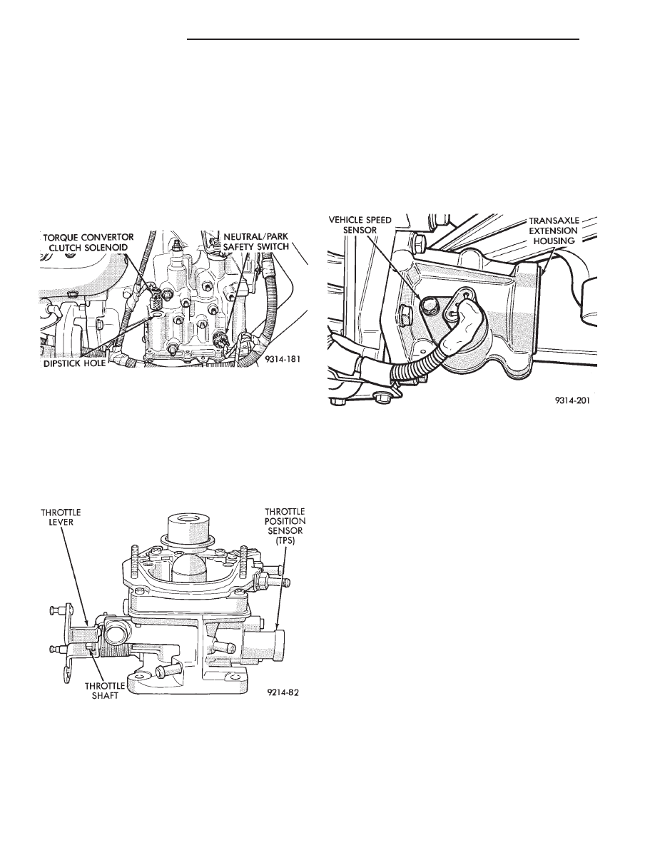
TRANSAXLE PARK/NEUTRAL SWITCH—PCM
INPUT
The park/neutral switch is located on the auto-
matic transaxle housing (Fig. 7). Manual transaxles
do not use park neutral switches. The switch pro-
vides an input to the PCM. The input indicates
whether the automatic transaxle is in Park, Neutral,
or a drive gear selection. This input is used to deter-
mine idle speed (varying with gear selection), fuel in-
jector pulse width, and ignition timing advance. The
park neutral switch is sometimes referred to as the
neutral safety switch.
THROTTLE POSITION SENSOR (TPS)—PCM INPUT
The Throttle Position Sensor (TPS) is mounted on
the throttle body and connected to the throttle blade
shaft (Fig. 8). The TPS is a variable resistor. The
sensor provides an input signal (voltage) to the PCM
representing throttle blade position. As the position
of the throttle blade changes, the resistance of the
TPS changes.
The PCM supplies approximately 5 volts to the
TPS. The TPS output voltage (input signal to the
PCM) represents the throttle blade position. The
PCM receives an input signal voltage from the TPS
varying in an approximate range of from 1 volt at
minimum throttle opening (idle) to 4 volts at wide
open throttle. Along with inputs from other sensors,
the PCM uses the TPS input to determine current
engine operating conditions. The PCM adjusts fuel
injector pulse width and ignition timing based on
these inputs.
VEHICLE SPEED SENSOR—PCM INPUT
The vehicle speed sensor is located in the transaxle
extension housing (Fig. 9). The sensor input is used
by the PCM to determine vehicle speed and distance
traveled.
The speed sensor generates 8 pulses per sensor rev-
olution. These signals, along with a closed throttle
signal from the TPS, determine if a closed throttle
deceleration
or
normal
idle
condition
(vehicle
stopped) exists. Under deceleration conditions, the
PCM adjusts the idle air control motor to maintain a
desired MAP value. Under idle conditions, the PCM
adjusts the idle air control motor to maintain a de-
sired engine speed.
AIR CONDITIONING (A/C) CLUTCH RELAY—PCM
OUTPUT
The PCM operates the air conditioning clutch relay
ground circuit. The radiator fan relay supplies bat-
tery power to the solenoid side of the A/C clutch re-
lay. The air conditioning clutch relay will not
energize unless the radiator fan relay energizes. The
PCM energizes the radiator fan relay when the air
conditioning or defrost switch is put in the ON posi-
tion and the low pressure and high pressure switches
close.
With the engine operating, the PCM cycles the air
conditioning clutch on and off when the A/C switch
closes with the blower motor switch in the on posi-
tion. When the PCM senses low idle speeds or wide
open throttle through the throttle position sensor, it
de-energizes the A/C clutch relay. The relay contacts
open, preventing air conditioning clutch engagement.
Fig. 7 Park/Neutral Switch
Fig. 8 Throttle Position Sensor
Fig. 9 Vehicle Distance (Speed) Sensor—Typical
14 - 28
FUEL SYSTEMS
Ä
Нет комментариевНе стесняйтесь поделиться с нами вашим ценным мнением.
Текст