Chrysler Le Baron, Dodge Dynasty, Plymouth Acclaim. Manual — part 28
On AC, AG and AJ models, the A/C clutch is lo-
cated in the power distribution center. Refer to the
Wiring and Component Identification section of
Group 8W.
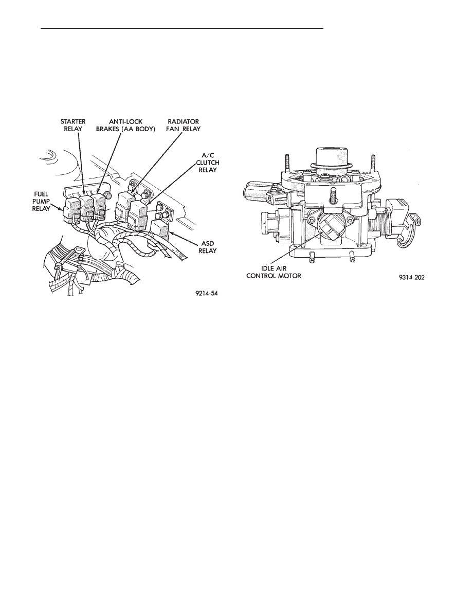
ON AA and AP models, the A/C clutch relay is
mounted to the inner fender panel, next to the driv-
ers side strut tower (Fig. 10).
AUTO SHUTDOWN (ASD) RELAY AND FUEL PUMP
RELAY—PCM OUTPUT
The PCM operates the auto shutdown (ASD) relay
and fuel pump relay through one ground path. The
PCM operates the relays by switching the ground
path on and off. Both relays turn on and off at the
same time.
The ASD relay connects battery voltage to the fuel
injector and ignition coil. The fuel pump relay con-
nects battery voltage to the fuel pump and oxygen
sensor heating element.
The PCM turns the ground path off when the igni-
tion switch is in the Off position. Both relays are off.
When the ignition switch is in the On or Crank po-
sition, the PCM monitors the distributor pick-up sig-
nal.
From
the
distributor
signal,
the
PCM
determines engine speed and ignition timing (coil
dwell). If the PCM does not receive a distributor sig-
nal when the ignition switch is in the Run position,
it will de-energize both relays. When the relays are
de-energized, battery voltage is not supplied to the
fuel injector, ignition coil, fuel pump and oxygen sen-
sor heating element.
On AC, AG and AJ models, the ASD relay and fuel
pump relay are located in the power distribution cen-
ter. Refer to the Wiring and Component Identifica-
tion section of Group 8W.
On AA and AP models, the ASD relay and fuel
pump relay are mounted on the drivers side fender
well, next to the strut tower (Fig. 10).
IDLE AIR CONTROL MOTOR—PCM OUTPUT
The idle air control motor is mounted on the throt-
tle body (Fig. 11). The PCM operates the idle air con-
trol motor. The PCM adjusts engine idle speed
through the idle air control motor to compensate for
engine load or ambient conditions.
The throttle body has an air bypass passage that
provides air for the engine at idle (the throttle blade
is closed). The idle air control motor pintle protrudes
into the air bypass passage and regulates air flow
through it.
The PCM adjusts engine idle speed by moving the
idle air control motor pintle in and out of the bypass
passage. The adjustments are based on inputs the
PCM receives from the throttle position sensor, speed
sensor (distributor pick-up coil), coolant temperature
sensor, and various switch operations (brake, park/
neutral, air conditioning). Deceleration die out is also
prevented by increasing airflow when the throttle is
closed quickly after a driving (speed) condition.
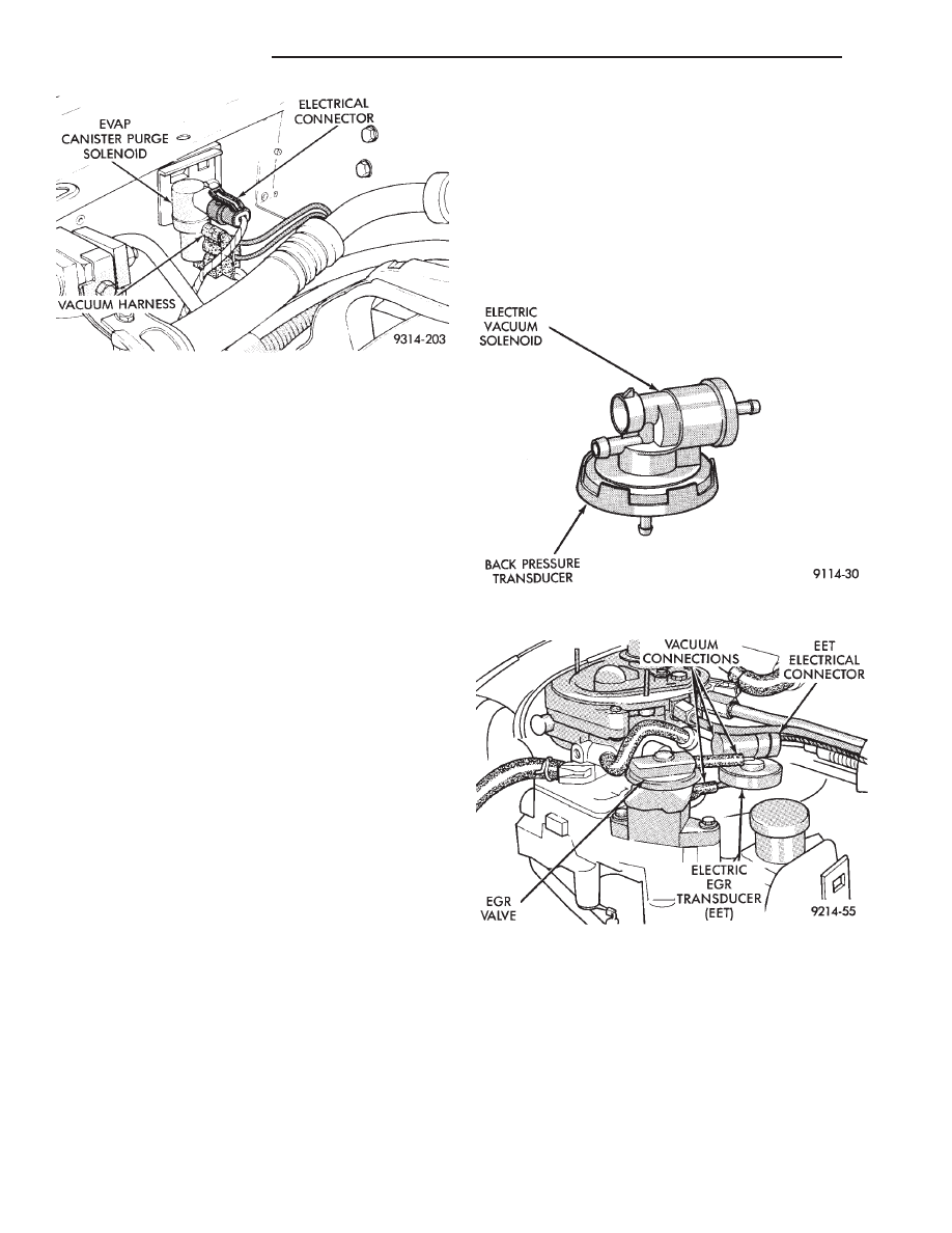
EVAP CANISTER PURGE SOLENOID—PCM
OUTPUT
Vacuum for the Evaporative Canister is controlled
by the EVAP Canister Purge Solenoid (Fig. 12). The
solenoid is controlled by the PCM.
The PCM operates the solenoid by switching the
ground circuit on and off based on engine operating
conditions. When grounded, the solenoid energizes
and prevents vacuum from reaching the evaporative
canister. When not energized, the solenoid allows
vacuum to flow to the canister.
During warm-up and for a specified time period af-
ter hot starts, the PCM grounds the purge solenoid.
Vacuum does not operate the evaporative canister
valve.
Fig. 10 Relay Identification
Fig. 11 Idle Air Control Motor
Ä
FUEL SYSTEMS
14 - 29
The PCM removes the ground to the solenoid when
the engine reaches a specified temperature and the
time delay interval has occurred. When the solenoid is
de-energized, vacuum flows to the canister purge
valve. Vapors are purged from the canister and flow to
the throttle body.
The purge solenoid is also energized during certain
idle conditions to update the fuel delivery calibration.
MALFUNCTION INDICATOR LAMP (CHECK
ENGINE)—PCM OUTPUT
The Malfunction Indicator lamp (instrument panel
Check Engine lamp) comes on each time the ignition
key is turned ON and stays on for 3 seconds as a bulb
test. The malfunction indicator lamp warns the opera-
tor that the PCM has entered a Limp-in mode. During
Limp-in-Mode, the PCM attempts to keep the system
operational. The malfunction indicator lamp signals
the need for immediate service. In limp-in mode, the
PCM compensates for the failure of certain components
that send incorrect signals. The PCM substitutes for
the incorrect signals with inputs from other sensors.
Signals that can trigger the Malfunction Indi-
cator Lamp.
• Coolant Temperature Sensor
• Manifold Absolute Pressure Sensor
• Throttle Position Sensor
• Battery Voltage Input
• An Emissions Related System
• Charging system
The malfunction indicator lamp can also be used to
display diagnostic trouble codes. Cycle the ignition
switch on, off, on, off, on, within five seconds and any
diagnostic trouble codes stored in the PCM will be
displayed. Refer to the 2.2L/2.5L Single Point Fuel
Injection—On-Board Diagnostics section in this group.
DATA LINK CONNECTOR—PCM OUTPUT
The data link connector provides the technician with
the means to connect the DRBII scan tool to diagnosis
the vehicle.
ELECTRIC ELECTRONIC GAS
RECIRCULATION—PCM OUTPUT
The electronic exhaust gas recirculation transducer
(EET) is a back pressure transducer/electric vacuum
solenoid assembly (Fig. 13). The EET assembly mounts
above the EGR valve (Fig. 14).
The solenoid turns the vacuum supply to the trans-
ducer on and off. The electric vacuum solenoid portion
of the EET energizes when the PCM provides a ground
path. When the solenoid energizes, vacuum is pre-
vented from flowing to the transducer. When the sole-
noid de-energizes, vacuum flows to the transducer. The
solenoid energizes during engine warm-up, closed
throttle (idle or cruise), wide open throttle, and rapid
acceleration/deceleration. If the solenoid wire con-
nector is disconnected, the EGR valve will oper-
ate at all times.
Fig. 12 EVAP Canister Purge Solenoid
Fig. 13 Electronic EGR Recirculation Transducer
Fig. 14 EGR Valve and Electric EGR Transducer
14 - 30
FUEL SYSTEMS
Ä
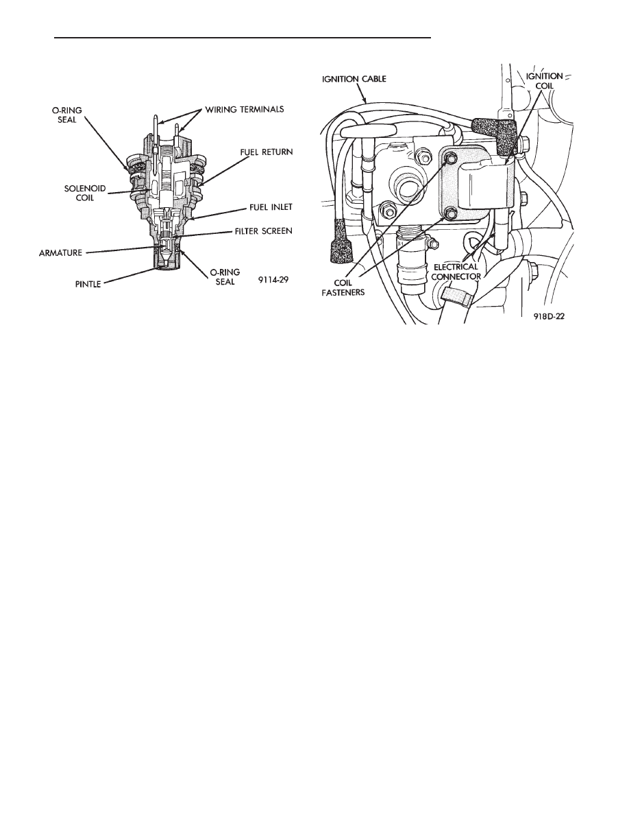
FUEL INJECTOR—PCM OUTPUT
The Fuel Injector is an electric solenoid operated
by the PCM (Fig. 15).
Based on sensor inputs, the PCM determines when
and how long the fuel injector should operate. The
amount of time the injector fires is referred to as in-
jector pulse width. The auto shutdown (ASD) relay
supplies battery voltage to the injector. The PCM
supplies the ground path. By switching the ground
path on and off, the PCM adjusts injector pulse
width. When the PCM supplies a ground path, a
spring loaded needle or armature lifts from its seat.
Fuel flows through the orifice and deflects off the
sharp edge of the injector nozzle. The resulting fuel
sprays forms a 45° cone shaped pattern before enter-
ing the air stream in the throttle body.
Fuel is supplied to the injector constantly at regu-
lated 270 Kpa (39 psi). Unused fuel returns to the
fuel tank.
GENERATOR FIELD—PCM OUTPUT
The PCM regulates the charging system voltage
within a range of 12.9 to 15.0 volts. Refer to Group
8A for charging system information.
IGNITION COIL—PCM OUTPUT
The PCM provides a ground contact (circuit) for en-
ergizing the ignition coil. When the PCM breaks the
contact, the energy in the coil primary transfers to
the secondary causing the spark. The PCM will de-
energize the ASD relay if it does not receive an input
from the distributor pick-up. Refer to Auto Shutdown
(ASD) Relay/Fuel Pump Relay—PCM Output in this
section for relay operation.
The ignition coil is mounted on the hot box next to
the thermostat housing (Fig. 16).
PART THROTTLE UNLOCK SOLENOID—PCM
OUTPUT
Three-speed automatic transaxles use a part throt-
tle unlock solenoid. The PCM controls the lock-up of
the torque convertor through the part throttle unlock
solenoid. The transaxle is locked up only in direct
drive mode. Refer to Group 21 for transaxle informa-
tion.
RADIATOR FAN RELAY—PCM OUTPUT
The radiator fan is energized by the PCM through
the radiator fan relay. The PCM grounds the radia-
tor fan relay when engine coolant reaches a predeter-
mined temperature. For more information, refer to
Group 7, Cooling Systems.
On AC, AG and AJ models, the radiator fan relay
is located in the power distribution center. Refer to
the Wiring and Component Identification section of
Group 8W.
On AA and AP models, the radiator fan relay is
mounted on the drivers side fender well, next to the
strut tower (Fig. 10).
SPEED CONTROL SOLENOIDS—PCM OUTPUT
The speed control vacuum and vent solenoids are
operated by the PCM. When the PCM supplies a
ground to the vacuum and vent solenoids, the speed
control system opens the throttle blade. When the
PCM supplies a ground only to the vent solenoid, the
throttle blade holds position. When the PCM removes
the ground from both the vacuum and vent solenoids,
the throttle blade closes. The PCM balances the two
solenoids to maintain the set speed. Refer to Group
8H for speed control information.
Fig. 15 Fuel Injector
Fig. 16 Ignition Coil
Ä
FUEL SYSTEMS
14 - 31
TACHOMETER—PCM OUTPUT
The PCM supplies engine RPM to the instrument
panel tachometer. Refer to Group 8 for tachometer
information.
MODES OF OPERATION
As input signals to the PCM change, the PCM
adjusts its response to the output devices. For example,
the PCM must calculate a different injector pulse
width and ignition timing for idle than it does for wide
open throttle (WOT). There are several different modes
of operation that determine how the PCM responds to
the various input signals.
There are two different areas of operation, OPEN
LOOP and CLOSED LOOP.
During OPEN LOOP modes, the PCM receives input
signals and responds according to preset PCM pro-
gramming. Input from the oxygen (O
2
) sensor is not
monitored during OPEN LOOP modes.
During CLOSED LOOP modes, the PCM does moni-
tor the oxygen (O
2
) sensor input. This input tells the
PCM if the calculated injector pulse width results in an
air-fuel ratio of 14.7 to 1. By monitoring the exhaust
oxygen content, the can PCM fine tune injector pulse
width for optimum fuel economy and low emissions.
The single point fuel injection system has the follow-
ing modes of operation:
• Ignition switch ON - Zero RPM
• Engine start-up
• Engine warm-up
• Cruise (Idle)
• Acceleration
• Deceleration
• Wide Open Throttle
• Ignition switch OFF
The engine start-up (cranking), engine warm-up, and
wide open throttle modes are OPEN LOOP modes. The
acceleration, deceleration, and cruise modes, with the
engine at operating temperature are CLOSED
LOOP modes (under most operating conditions).
IGNITION SWITCH ON (ZERO RPM) MODE
When the single point fuel injection system is acti-
vated by the ignition switch, the following actions
occur:
• The PCM determines atmospheric air pressure from
the MAP sensor input to calculate basic fuel strategy.
• The PCM monitors the coolant temperature sensor
and throttle position sensor inputs. The PCM modifies
fuel strategy based on these inputs.
When the key is in the ON position and the engine is
not running, the (ASD) and fuel pump relays are not
energized. Therefore, battery voltage is not supplied to
the fuel pump, ignition coil, fuel injector or oxygen
sensor heating element.
ENGINE START-UP MODE
This is an OPEN LOOP mode. The following actions
occur when the starter motor is engaged.
If the PCM receives a distributor signal it energizes
the auto shutdown (ASD) relay and fuel pump relay to
supply battery voltage to the fuel injector, ignition coil
and oxygen sensor heating element. If the PCM does
not receive a distributor input, it de-energizes the ASD
and fuel pump relays after approximately one second.
When the engine idles within
664 RPM of the target
RPM, the PCM compares the current MAP value with
the atmospheric pressure value it received during the
Ignition Switch On (Zero RPM) Mode. If a minimum
difference between the two is not detected, a MAP
sensor fault is set into memory.
Once the ASD relay and fuel pump relay have ener-
gized, the PCM:
• Supplies a ground path to the injector. The injector
is pulsed four times per engine revolution instead of
the normal two pulses per revolution.
• Determines injector pulse width based on coolant
temperature, MAP sensor input, throttle position, and
the number of engine revolutions since cranking was
initiated.
• Monitors the coolant temperature sensor, distribu-
tor pick-up, MAP sensor, and throttle position sensor to
determine correct ignition timing.
ENGINE WARM-UP MODE
This is a OPEN LOOP mode. The following inputs
are received by the PCM:
• coolant temperature
• manifold absolute pressure (MAP)
• engine speed (distributor pick-up)
• throttle position
• A/C switch
• battery voltage
The PCM provides a ground path for the injector to
precisely control injector pulse width (by switching the
ground on and off) and fires the injector twice per
engine revolution. The PCM regulates ignition timing.
It also adjusts engine idle speed through the idle air
control motor.
CRUISE OR IDLE MODE
When the engine is at operating temperature this is
a CLOSED LOOP mode. During cruising speed and at
idle the following inputs are received by the PCM:
• coolant temperature
• manifold absolute pressure
• engine speed
• throttle position
• exhaust gas oxygen content
• A/C control positions
• battery voltage
14 - 32
FUEL SYSTEMS
Ä
Нет комментариевНе стесняйтесь поделиться с нами вашим ценным мнением.
Текст