Chrysler Le Baron, Dodge Dynasty, Plymouth Acclaim. Manual — part 150

GUIDE ASSEMBLY INSTALLATION
(1) Install guide cable into rear of guide assembly.
(2) Install guide assembly at an angle so the rear
portion slips under finger clips at rear of module
housing.
(3) Place cable in groove of cable holder.
(4) Install screws in track assembly.
(5) Install locators.
(6) Reverse removal operation.
WINDSHIELD
SAFETY PRECAUTIONS AND WARNINGS
WARNING: DO NOT OPERATE VEHICLE FOR AT
LEAST 24 HOURS AFTER WINDSHIELD INSTALLA-
TION. WINDSHIELD MAY NOT PERFORM PROPERLY
IN THE EVENT OF A COLLISION IF URETHANE AD-
HESIVE IS NOT SUFFICIENTLY CURED. REFER TO
MANUFACTURER OF URETHANE BEING USED FOR
CURING TIME SPECIFICATIONS.
WHEN INSTALLING GLASS, DO NOT USE URE-
THANE ADHESIVE AFTER DATE ON PRODUCT HAS
EXPIRED.
SAFETY
AND
QUALITY
OF
REPAIR
WOULD BE QUESTIONABLE.
DO NOT USE URETHANE ADHESIVE OR PRIMER IN
CLOSED WORK AREA, PERSONAL INJURY CAN RE-
SULT.
PROTECT SKIN FROM COMING IN CONTACT WITH
URETHANE, PERSONAL INJURY CAN RESULT.
WEAR EYE AND HAND PROTECTION WHEN
WORKING WITH GLASS, PERSONAL INJURY CAN
RESULT.
CAUTION: Protect all painted or trimmed surfaces
from coming in contact with urethane or primers,
damage will result.
Do not damage painted surfaces when removing
mouldings or cutting urethane around windshield.
It is difficult to salvage a windshield during the
removal operation. The windshield is part of the struc-
tural support for the roof. The urethane bonding used
to secure the windshield to the fence is difficult to cut
or clean from any surface. If the mouldings are set in
urethane, it would also be unlikely they could be
salvaged. Before removing the windshield, check the
availability of the windshield and mouldings from the
parts supplier.
WINDSHIELD REMOVAL
(1) Remove inside rear view mirror.
(2) Remove cowl cover.
(3) Remove windshield mouldings using a suitable
hook tool and trim stick (Fig. 1).
(4) Cut urethane bonding from around windshield
using a suitable sharp cold knife. A pneumatic cutting
device can be used if available (Fig. 2).
(5) Separate windshield from vehicle.
WINDSHIELD INSTALLATION
CAUTION: Open the left front door glass before
installing windshield to avoid pressurizing the pas-
senger compartment if a door or the trunk lid is
slammed before urethane bonding is cured. Water
leaks can result.
Fig. 8 Guide Assembly
Fig. 1 Windshield Mouldings
Fig. 2 Cut Urethane Around Windshield
Ä
BODY
23 - 9
Allow the urethane at least 24 hours to cure before
returning the vehicle to use.
The windshield fence should be cleaned of old ure-
thane bonding material. Support spacers should be
cleaned and properly installed on weld studs or re-
pair screws at bottom of windshield opening.
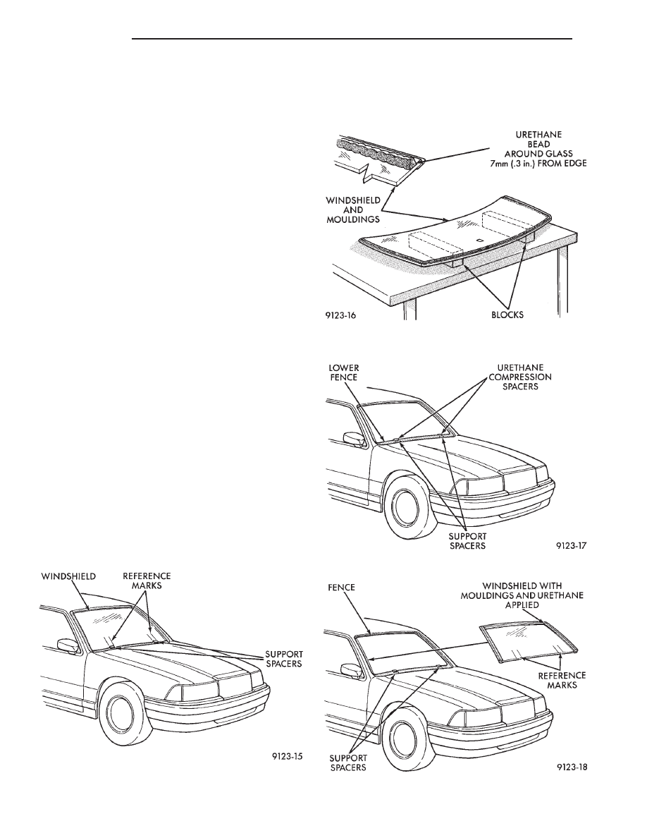
(1) Place replacement windshield into windshield
opening and position glass in the center of the open-
ing against the support spacers. Mark the glass at
the support spacers with a grease pencil or pieces of
masking tape and ink pen to use as a reference for
installation. Remove replacement windshield from
windshield opening (Fig. 3).
(2) Position the windshield inside up on a suitable
work surface with two padded, wood 10 cm by 10 cm
by 50 cm (4 in. by 4 in. by 20 in.) blocks, placed par-
allel 75 cm (2.5 ft.) apart (Fig. 4).
(3) Clean inside of windshield with Mopar Glass
Cleaner and lint-free cloth.
(4) Apply clear glass primer 25 mm (1 in.) wide
around perimeter of windshield and wipe with clean/
dry lint-free cloth.
(5) Install mouldings on windshield (Fig. 4).
(6) Apply black-out primer 15 mm (.75 in.) wide on
top and sides of windshield and 25 mm (1 in.) on bot-
tom of windshield. Allow at least three minutes dry-
ing time.
(7) Position windshield bonding compression spac-
ers on lower fence above the support spacers at the
edge of the windshield opening (Fig. 5).
(8) Apply a 10 mm (0.4 in.) bead of urethane
around perimeter of windshield along the inside of
the mouldings.
(9) With the aid of a helper, position the wind-
shield over the windshield opening. Align the refer-
ence marks at the bottom of the windshield to the
support spacers.
(10) Slowly lower windshield glass to windshield
opening fence. Guide the top moulding into proper
position if necessary. Push windshield inward to
fence spacers at bottom and until top moulding is
flush to roof line (Fig. 6).
(11) Clean excess urethane from exterior with Mo-
par, Super Clean or equivalent.
(12) Install cowl cover and wipers.
(13) Install inside rear view mirror.
(14) After urethane has cured, water test wind-
shield to verify repair.
Fig. 3 Center Windshield and Mark at Support
Spacers
Fig. 4 Work Surface Set-up and Mouldings
Installation
Fig. 5 Position Urethane Compression Spacers
Fig. 6 Lower Windshield Into Position
23 - 10
BODY
Ä

AA-VEHICLE BODY COMPONENT SERVICE
INDEX
page
page
A-Pillar and Roof Rail Mouldings
. . . . . . . . . . . . . . . . . . . . . . . 25
Body Side Moulding and Applique
. . . . . . . . . . . . . . . . . . . . . . . . . . . . . 13
Cowl Panel Trim and Scuff Plates
. . . . . . . . . . . . . . . . 24
. . . . . . . . . . . . . . . . . . . . . . . . . . . . 30
. . . . . . . . . . . . . . . . . . . . . 29
. . . . . . . . . . . . . . . . . . . . . 15
Front Door Belt Moulding and Weatherstrip
. . . . . . . . . . . . . . . . . . . . . . . . 17
Front Door Glass Channel and Run Weatherstrip
Front Door Glass Run Lower Channel
. . . . . . . . . . . . . . . . . . . . . . . . . 16
. . . . . . . . . . . . . . . . 17
Front Door Silencer and Water Shield
. . . . . . . . . . . . . . . . . . . . 14
Front Door Window Regulator/Manual
Front Door Window Regulator/Power
. . . . . . . . . . . . . . . . . . 13
. . . . . . . . . . . . . . . . . . . . . . . . . . . . 14
Front Power Door Lock Actuator
. . . . . . . . . . . . . . . . . . . . . . . . . 27
. . . . . . . . . . . . . . . . . . . . . . . . . . . . . 28
. . . . . . . . . . . . . . . . . . . . . . . . . . . 36
. . . . . . . . . . . . . . . . . . . . . . . . . . . . . . . . . . 11
. . . . . . . . . . . . . . . . . . . . . . . . . . . . . 30
. . . . . . . . . . . . . . . . . . . . . . . . 11
. . . . . . . . . . . . . . 12
Outside Front Door Latch Release Handle
Outside Rear Door Latch Release Handle
. . . . . . . . . . . . . . . . . . . . . . . . 30
. . . . . . . . . . . . . . . 27
. . . . . . . . . . . . . . . . . . . . . . . 27
. . . . . . . . . . . . . . . . . . . . 31
. . . . . . . . . . . . . . . . . . . . . 20
Rear Door Belt Moulding and Weatherstrip
. . . . . . . . . . . . . . . . . . . . . . . . . 22
Rear Door Glass Run Weatherstrip
Rear Door Glass Stationary Glass Module
. . . . . . . . . . . . . . . . . . . . . . . . . 21
Rear Door Silencer and Water Shield
. . . . . . . . . . . . . . . . . . . . . 20
Rear Door Window Regulator/Manual
Rear Door Window Regulator/Power
. . . . . . . . . . . . . . . . . . . . . . . . . . 28
. . . . . . . . . . . . . . . . . . . . . . . . . . . . . 28
. . . . . . . . . . . . . . . . . . . . . 27
. . . . . . . . . . . . . . . . . . . . . . 32
. . . . . . . . . . . . . . . . . . . . 31
. . . . . . . . . . . . . . . . . . . . 31
. . . . . . . . . . . . . . . . . . . . 31
. . . . . . . . . . . . . . . . . . . . . . . . . . . . . . 33
. . . . . . . . . . . . . . . . . . . . . . . . . 34
. . . . . . . . . . . . . . . . . . . . . . . . . . 34
. . . . . . . . . . . . . . . . . . . . . . . . . . 34
. . . . . . . . . . . . . . . . . . . 35
. . . . . . . . . . . . . . . . . . . . . 34
. . . . . . . . . . . . . . . . . . . . . . . . . . . . 35
. . . . . . . . . . . . . . . . 35
. . . . . . . . . . . . . . . . . . . . . . . . 31
GRILLE
REMOVAL (FIG. 1)
(1) Raise hood to full up position.
(2) Remove hood safety catch release rod retainer
and separate rod from grille.
(3) Remove grille end reinforcement attaching
bolts.
(4) Remove nuts holding grille to hood.
(5) Separate grille from hood.
INSTALLATION
Reverse the preceding operation.
HOOD AND HINGES
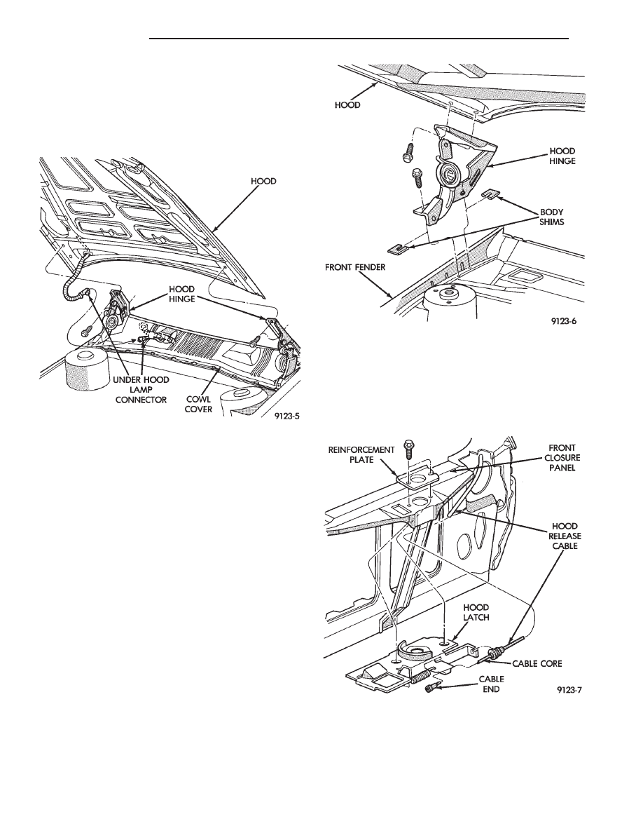
HOOD REMOVAL (FIG. 2)
(1) Raise hood to full up position.
(2) Lift front edge of cowl cover on the right side of
the windshield washer bottle and disconnect the un-
der hood lamp wire connector.
(3) Mark all bolt and hinge attachment locations
with a grease pencil or other suitable device to pro-
vide reference marks for installation. When install-
ing hood, align all marks and secure bolts. The hood
should be aligned to 4 mm (0.160 in.) gap to the front
fenders and flush across the top surfaces along fend-
ers.
(4) Remove the top hood to hinge attaching bolts
and loosen the bottom bolts until they can be re-
moved by hand.
Fig. 1 Grille Assembly
Ä
AA-BODY
23 - 11
(5) With assistance of a helper at the opposite side
of the vehicle to support the hood, remove the bottom
hood to hinge attaching bolts. Separate the hood
from the vehicle.
HOOD INSTALLATION
Reverse the preceding operation.
HOOD HINGE REMOVAL (FIG. 3)
(1) Support hood on the side that requires hinge
replacement.
(2) Mark all bolt and hinge attachment locations
with a grease pencil or other suitable device to pro-
vide reference marks for installation. When install-
ing hood hinge, align all marks and secure bolts. The
hood should be aligned to 4 mm (0.160 in.) gap to the
front fenders and flush across the top surfaces along
fenders. Shims can be added or removed under hood
hinge to achieve proper hood height.
(3) Remove hood to hinge attaching bolts.
(4) Remove hood hinge to front fender attaching
bolts and separate hinge from vehicle.
HOOD HINGE INSTALLATION
Reverse the preceding operation. If necessary, paint
new hinge before installation.
HOOD LATCH AND RELEASE CABLE
HOOD LATCH REMOVAL (FIG. 4)
(1) Raise hood top the full up position.
(2) Remove hood latch attaching bolts holding
latch to radiator closure panel and separate from ve-
hicle.
(3) Pry release cable casing attachment from slot
receiver on latch, disengage cable end from latch arm
hook.
HOOD LATCH INSTALLATION
Reverse the preceding operation.
HOOD LATCH RELEASE CABLE REMOVAL
(FIG. 5)
(1) Raise hood to the full up position.
Fig. 2 Hood Assembly
Fig. 3 Hood Hinge Assembly
Fig. 4 Hood Latch Assembly
23 - 12
AA-BODY
Ä
Нет комментариевНе стесняйтесь поделиться с нами вашим ценным мнением.
Текст