Chrysler Le Baron, Dodge Dynasty, Plymouth Acclaim. Manual — part 149
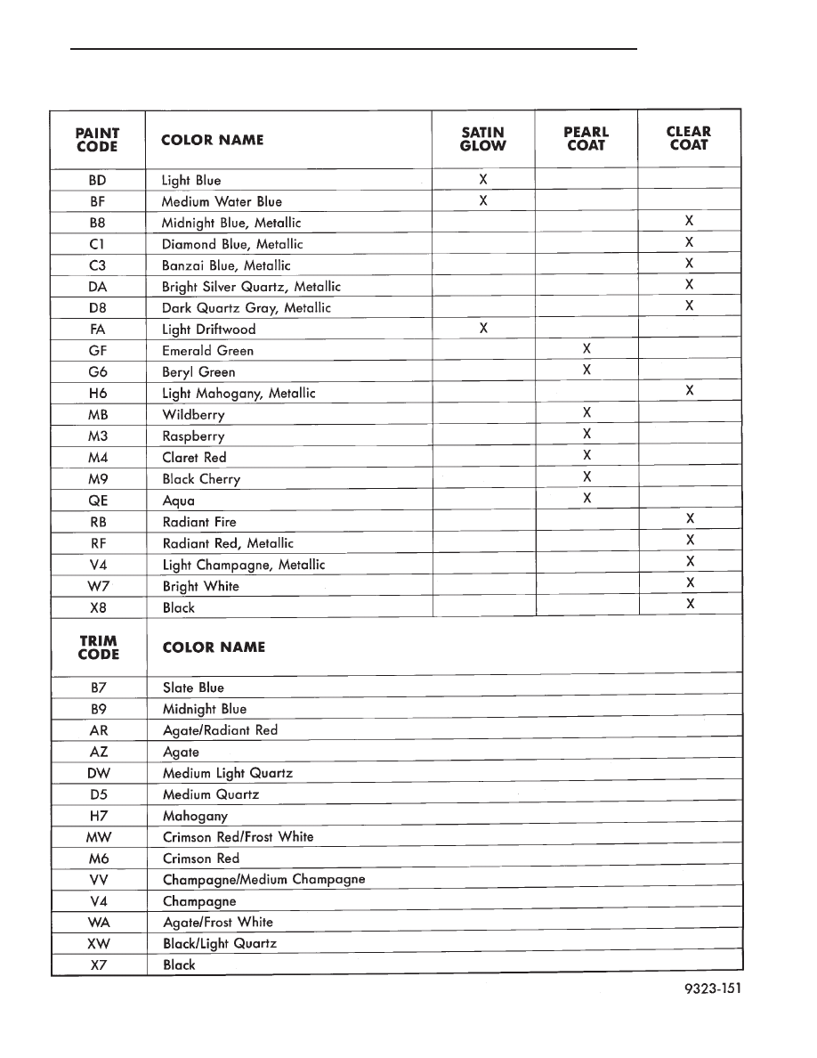
PAINT AND TRIM CODE DESCRIPTIONS
Ä
BODY
23 - 5

POWER SUNROOF
INDEX
page
page
. . . . . . . . . . . . . . . . . . . . . . . . 7
. . . . . . . . . . . . . . . . . . . . . . . . . . . . 7
. . . . . . . . . . . . . . . . . . . . . . . 7
. . . . . . . . . . . . . . . . . . . . . . . . . . . . . 8
. . . . . . . . . . . . . . . . . . . . . . . . 6
. . . . . . . . . . . . . . . . . . . . . . . . . . . . . 7
Glass Vertical Height Adjustment
. . . . . . . . . . . . . . . . . . . . . . . . . . 8
. . . . . . . . . . . . . . . . . . . . . 7
. . . . . . . . . . . . . . . . . . . . . . . . . . . . . . . 8
. . . . . . . . . . . . . . . . . . . . . . . . . . . 6
GENERAL INFORMATION
All sunroofs are equipped with drain tubes that are
located in the A, B or C-pillars. The drain tubes
must be kept open to prevent water from entering
the passenger compartment.
LUBRICATION
(1) Lubricate cables with Lubriplate or equivalent
when cables are replaced.
(2) Periodically clean dirt from guide rail covers.
DRAIN TUBES
• Inspect the drain holes, located in the trough
around the sunroof opening to verify they are clear.
Inspection should be performed at least once a year
or when problems are suspected. If drain hose or
tubes are plugged, use compressed air or blunt flexi-
ble wire to clear them. If tubes cannot be cleared,
they must be repaired.
• The lower ends of the rear drain tubes are located
in the rear quarter panel drop wells. To clear rear
drain tubes, use compressed air or blunt flexible wire
from the lower ends of the tubes.
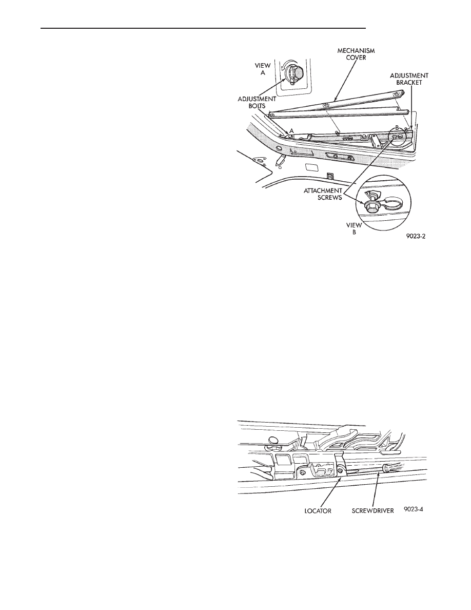
GLASS VERTICAL HEIGHT ADJUSTMENT
GLASS VERTICAL ADJUSTMENT (FIG. 1)
(1) Open glass to vent position.
(2) Slide upper half of mechanism covers rearward
until clips disengage and separate covers from vehi-
cle.
(3) Close glass panel, separately loosen adjusting
bolts and individually adjust the corners of glass.
(4) Adjust front of glass panel to 1.0 mm (0.040 in.)
below top surface of roof panel.
(5) Adjust rear of glass to 1.0 mm (0.040 in.) above
top surface of roof panel.
(6) Secure adjustment bolts and install cover.
WIND DEFLECTOR
WIND DEFLECTOR REMOVAL (FIG. 2)
(1) Open sun roof glass panel.
(2) Remove screws holding wind deflector to sun
roof unit side rail.
(3) Separate wind deflector from vehicle.
WIND DEFLECTOR INSTALLATION
Reverse the preceding operation.
WIND DEFLECTOR ADJUSTMENT (FIG. 2)
(1) Open sunroof.
Fig. 1 Glass Adjustment
Fig. 2 Deflector Assembly
23 - 6
BODY
Ä
(2) position wind deflector so 19 mm (0.75 in.)
above top surface of roof panel and 1 mm (0.040 in.)
rearward of roof panel forward edge.
(3) Secure wind deflector to sunroof unit.
GLASS PANEL
GLASS PANEL REMOVAL
(1) Remove wind deflector mechanism covers (Fig.
1).
(2) Position glass to vent position.
(3) Position sunshade full rearward.
(4) Loosen nuts holding glass panel to side adjust-
ment brackets.
(5) Slide glass panel rearward 12 mm (0.5 in.) and
separate glass from sunroof unit.
GLASS PANEL INSTALLATION
(1) Position glass panel in opening with logo rear-
ward and slide panel forward 12 mm (0.5 in.).
(2) Verify that attaching nuts are below top sur-
face of glass adjustment brackets.
(3) Close sunroof to center glass panel in roof open-
ing.
(4) Tighten center screws to hold adjustment.
(5) Open glass to vent position and tighten nuts to
8 N
Im (70.8 in-lbs.).
(6) Close glass and check alignment.
(7) Install the mechanism covers.
(8) Adjust wind deflector, if necessary.
ADJUSTMENT BRACKET
ADJUSTMENT BRACKET REMOVAL (FIG. 3)
(1) Remove wind deflector, mechanism covers and
glass panel.
(2) Move glass carriage to vent position and re-
move rearward adjustment bolt from adjustment
bracket.
(3) Lift rear of adjustment bracket to highest ver-
tical position and disengage front of bracket from
unit.
ADJUSTMENT BRACKET INSTALLATION
Reverse the preceding operation. Adjust glass, and
wind deflector as necessary.
DRAIN CHANNEL
DRAIN CHANNEL REMOVAL
(1) Remove wind deflector mechanism covers and
glass panel.
(2) Locate glass carriage to vent position and drain
channel in full forward position.
(3) Remove screws holding drain channel to sup-
port frame.
DRAIN CHANNEL INSTALLATION
Reverse the preceding operation.
DRIVE CABLE LOCATORS
DRIVE CABLE LOCATORS REMOVAL (FIG. 4)
(1) Position glass 19 mm (0.75 in.) until rearward
until cable locator is visible.
(2) Remove screws holding drive cable locator to
unit.
(3) Remove travel limiting micro switch grommet
and disconnect wire connector.
(4) Insert a small screwdriver under rear edge of
locator and pry locator from track.
DRIVE CABLE LOCATORS INSTALLATION
Reverse the preceding operation. The small out-
board lip underneath cable locator slips under bottom
slot on guide track. After locator is seated install
screws.
MOTOR AND DRIVE GEARS
MOTOR AND DRIVE GEAR REMOVAL (FIG. 5)
(1) Open sunroof to vent position.
(2) Remove head lining.
Fig. 3 Glass Height Vertical Adjustment
Fig. 4 Removing Cable Drive Locator
Ä
BODY
23 - 7

(3) Remove bolts holding sunroof motor to motor
bracket.
(4) Disconnect wire connector.
(5) Separate motor and drive gear from drive ca-
bles.
MOTOR AND DRIVE GEAR INSTALLATION
(1) Verify that sunroof is in vent position. Push
mechanism forward on both sides to align drive ca-
bles.
(2) Engage drive gears onto drive cables.
(3) Install motor and drive gear screws and tighten
to 5 N
Im (44 in-lbs.).
(4) Install head lining.
DRIVE CABLES
DRIVE CABLES REMOVAL (FIG. 6)
(1) Open sunroof to vent position.
(2) Remove head lining, wind deflector, mechanism
covers, glass panel, side glass adjustment brackets,
motor and drive cable locators.
(3) Lift cable out of cable retainer and pull for-
ward. Separate cable from assembly.
DRIVE CABLES INSTALLATION
Verify sunroof is in vent position. Push mechanism
forward on both sides to align drive cables. Reverse
the preceding operation.
SUNSHADE
SUNSHADE REMOVAL (FIG. 7)
(1) Remove wind deflector, mechanism covers and
glass panel.
(2) Position system to full rearward position.
(3) Slide sunshade panel full forward and release
the front tabs from track assembly.
(4) Pull rear retaining clip inboard and lift sun
shade out.
SUNSHADE INSTALLATION
Reverse the preceding operation.
GUIDE ASSEMBLY
GUIDE ASSEMBLY REMOVAL (FIG. 8)
(1) Remove wind deflector, mechanism covers, glass
panel, drain channel, sunshade and drive cable locator
as necessary.
(2) Move glass carriage to vent position.
(3) Remove front slide from guide assembly.
(4) Remove screws holding front and center guide
track to unit.
(5) Pull cable out of groove for cable end.
(6) Pull guide outward to release from housing.
Separate rear end of guide from clips. Slide guide out of
unit.
Fig. 5 Sunroof Motor and Drive Gear
Fig. 6 Drive Cables
Fig. 7 Sunshade Assembly
23 - 8
BODY
Ä
Нет комментариевНе стесняйтесь поделиться с нами вашим ценным мнением.
Текст