Chrysler Le Baron, Dodge Dynasty, Plymouth Acclaim. Manual — part 245

INSTALLATION
(1) Connect the wheel speed sensor connector to
the wiring harness.
(2) Push sensor assembly grommet into hole in
fender shield. Install clip and screw.
(3) Install the 2 screws that fasten the speed sen-
sor routing tube to the frame rail.
(4) Install sensor grommets in brackets on fender
shield and strut damper.
(5) Coat the speed sensor with High Temperature
Multi-purpose E.P. Grease before installing into the
steering knuckle. Install screw tighten to 7 N
Im (60
in. lbs.)
CAUTION: Proper installation of wheel speed sen-
sor cables is critical to continued system operation.
Be sure that cables are installed in retainers. Fail-
ure to install cables in retainers, as shown in this
section, may result in contact with moving parts
and/or over extension of cables, resulting in an
open circuit.
REAR WHEEL SPEED SENSOR (FIGS. 13 AND
14)
REMOVAL
(1) Raise vehicle and remove wheel and tire as-
sembly.
(2) Remove sensor assembly grommet from under-
body and pull harness through hole in underbody.
(3) Unplug connector from harness.
(4) Remove
sensor
assembly
grommets
from
bracket which is screwed into the body hose bracket,
just forward of trailing arm bushing (batwing brack-
et.)
(5) Remove sensor and brake tube assembly clip,
located on the inboard side of trailing arm.
(6) Remove sensor wire fastener from rear brake
hose bracket.
(7) Remove outboard sensor assembly retainer nut.
This nut also is used to capture the brake tube clip.
(8) Remove sensor head screw.
(9) Carefully, remove sensor head from adapter as-
sembly. If the sensor has seized, due to corrosion, DO
NOT USE PLIERS ON SENSOR HEAD. Use a ham-
mer and a punch and tap edge of sensor ear, rocking
the sensor side to side until free.
INSTALLATION
Installation is reverse order of removal. Be sure to
coat sensor with High Temperature Multi-purpose
E.P. Grease before installing into adapter assembly.
Tighten screw to 7 N
Im (60 in. lbs.) torque.
Fig. 13 Rear Wheel Speed Sensor Routing at Trailing Arm
Ä
ANTI-LOCK 6 BRAKE SYSTEM
5 - 133
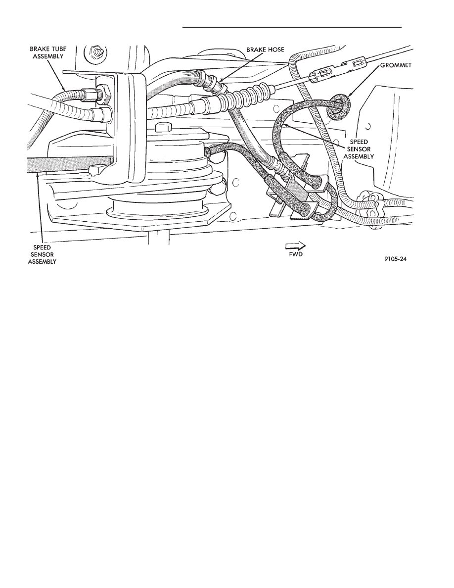
Fig. 14 Body Routing of Rear Speed Sensor Wiring
5 - 134
ANTI-LOCK 6 BRAKE SYSTEM
Ä
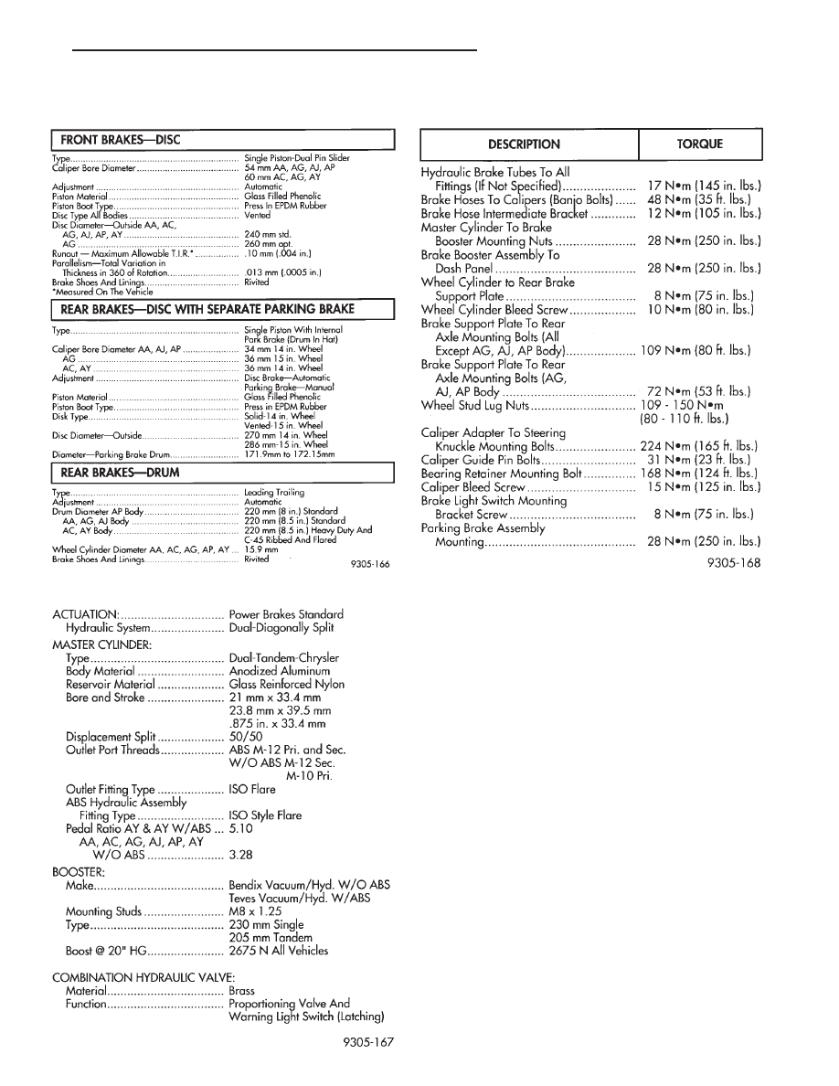
SPECIFICATIONS
SPECIFICATIONS METRIC
BRAKE ACTUATION SYSTEM
TIGHTENING REFERENCE
Ä
ANTI-LOCK 6 BRAKE SYSTEM
5 - 135
Нет комментариевНе стесняйтесь поделиться с нами вашим ценным мнением.
Текст