Chrysler Le Baron, Dodge Dynasty, Plymouth Acclaim. Manual — part 244
INSTALLATION
(1) Install the Modulator Assembly in the vehicle.
Use the protruding tab on the Modulator Assembly
to locate and hold the assembly in place in the vehi-
cle. Make sure the bracket is held by the front
mounting bolt.
(2) Install but do not tighten the Modulator As-
sembly bracket to fender shield attaching bolt.
(3) Raise the vehicle on the hoist. Install the Mod-
ulator Assembly bracket mounting bolt near the
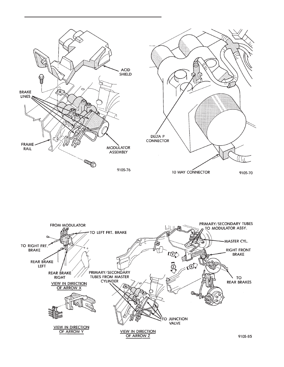
Fig. 2 Modulator Assembly Removal
Fig. 3 Modulator Assembly Electrical Connections
Fig. 4 Brake Tube and Hose Routing at Modulator Assembly
Ä
ANTI-LOCK 6 BRAKE SYSTEM
5 - 129
junction block. Torque both lower mounting bracket
bolts to 28 N
Im (250 in. lbs.)
(4) Reinstall the 4 hydraulic brake tubes to the
Modulator Assembly and torque the fittings to 16
N
Im (145 in. lbs.).
(5) Reconnect the 10 way Modulator assembly con-
nector, and the delta P switch connector.
(6) Lower the vehicle and install the 2 master cyl-
inder supply tubes to the Modulator Assembly.
Torque the Modulator Assembly fittings and the
master cylinder fittings to 16 N
Im (145 in.lbs.).
(7) Torque the Modulator to fender splash shield
attaching bolt to 28 N
Im (250 in. lbs.)
(8) Bleed the brake system. Refer to the Bleeding
Bendix Anti 6 Brake System in this section of the
manual for proper bleeding procedure.
(9) Reinstall the acid shield and battery tray. Re-
install battery and connect battery cables.
MASTER CYLINDER AND POWER BOOSTER
REMOVAL AND INSTALLATION
If the Master Cylinder or the Power Booster need
to be serviced or replaced. Refer to Master Cylinder
or Power Brake Service section in this group of the
service manual.
After servicing the Master Cylinder. Refer back to
this section of the service manual. For the appropri-
ate procedure and sequence, used to bleed the base
and ABS portion of the brake system
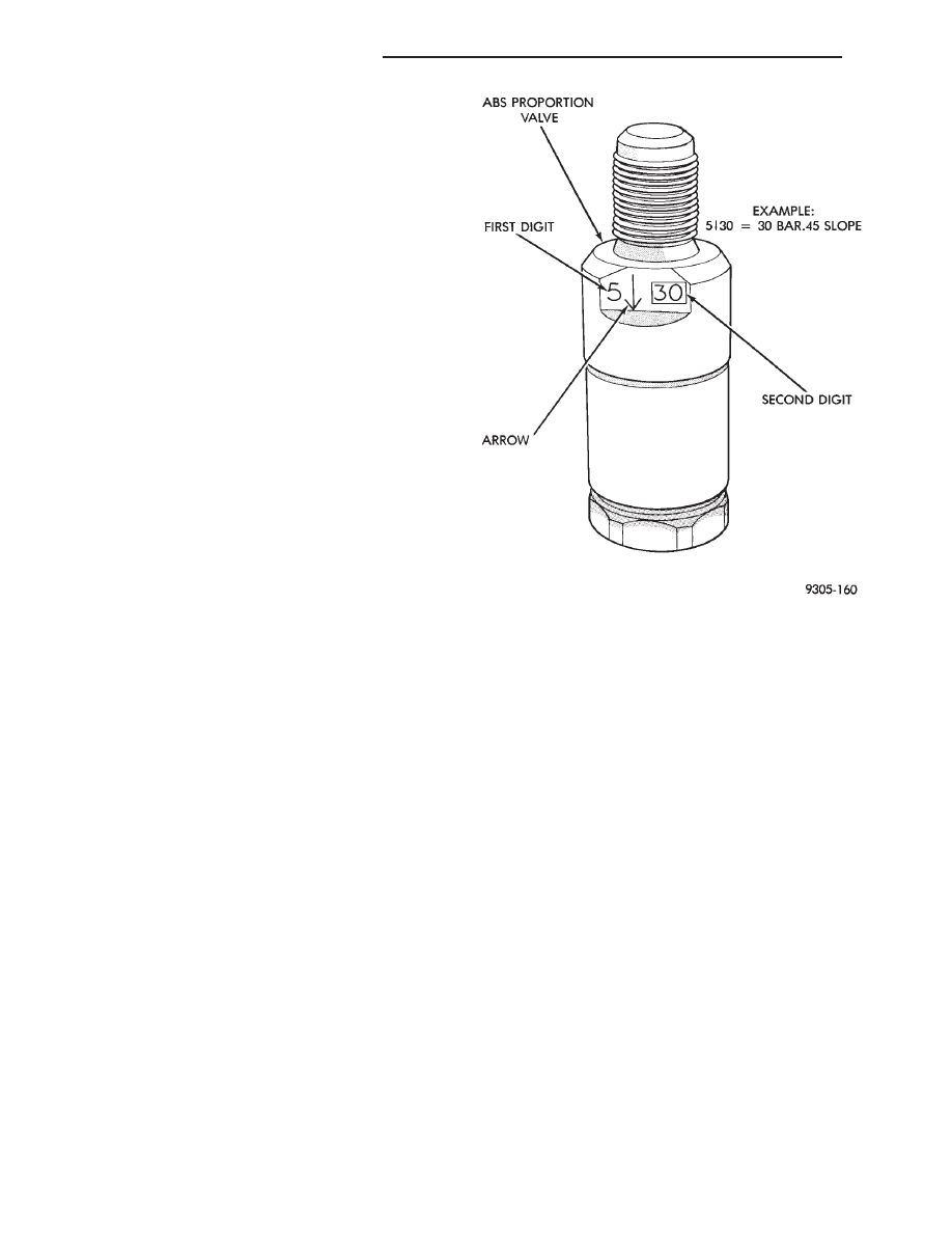
PROPORTIONING VALVES (FIG. 5)
CAUTION: Proportioning valves should never be
disassembled.
REMOVAL
(1) Remove brake tube and fitting from proportion-
ing valve.
(2) Remove proportioning valve from Modulator
Assembly.
INSTALLATION
(1) Install proportioning valve on Modulator As-
sembly and tighten to 40 N
Im (30 ft. lbs.) torque.
(2) Install brake tube on proportioning valve.
Tighten tube nut to 15 N
Im (11 ft. lbs.) torque.
(3) Bleed the affected brake line, see Bleeding Ben-
dix Anti Lock 6 Brake System in this section of the
manual.
ELECTRONIC COMPONENTS
CONTROLLER ANTI-LOCK BRAKE (CAB)
REMOVAL
(1) Turn vehicle ignition off.
(2) Disconnect the wiring harness connectors from
the Anti-Lock relays (Fig. 6). Relays will be removed
as part of the (CAB) bracket.
(3) Disconnect the wiring harness 60 way connec-
tor (Fig. 6) from the Controller Anti-Lock Brake
Module (CAB). VERIFY THAT THE VEHICLE
IGNITION IS OFF BEFORE REMOVING THE
60 WAY CONNECTOR.
(4) Remove the 2 (CAB) module bracket, to frame
rail mounting bolts (Fig. 6)
(5) Remove the (CAB) module from the vehicle.
(6) Remove the 3 (CAB) to bracket mounting
screws and remove the (CAB) from the mounting
bracket (Fig. 7).
INSTALLATION
The Controller Anti-Lock Brake (CAB) module in-
stallation is done in the reverse order of removal.
REMOVAL/INSTALLATION OF SYSTEM AND
WARNING LAMP RELAY
The System and Warning Lamp relay are both ser-
viced together as an assembly, with the mounting
bracket. They are mounted to a separate bracket that
is attached to the (CAB) bracket assembly (Fig. 8).
Fig. 5 ABS Proportioning Valve Identification
5 - 130
ANTI-LOCK 6 BRAKE SYSTEM
Ä
REMOVE
(1) Hold the relays with one hand, while pulling
strait down on the wiring harness connector. Until
the connectors are free from the relays (do not twist
the connectors).
(2) Remove the screw (Fig. 9) holding the relay
bracket to the (CAB) bracket. Remove the relays and
bracket assembly
INSTALL
(1) Mount the relay and bracket assembly to the
(CAB) bracket, with the mounting screw (Fig. 9).
(2) Holding the relays with one hand, push the
wiring harness connector strait onto the terminals of
the relay. Make sure the connector is fully seated
onto the terminals of the relay.
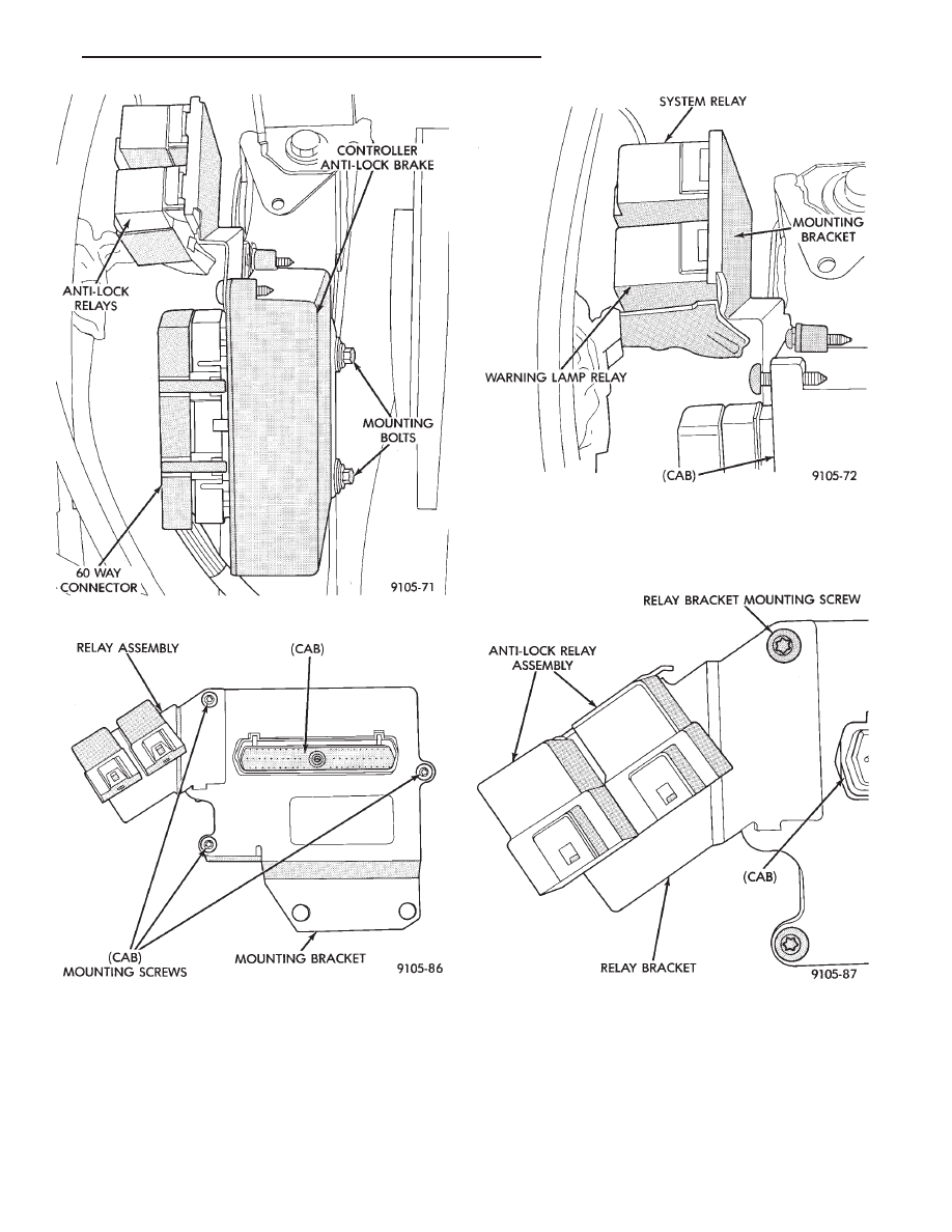
Fig. 6 Location Controller Anti-Lock Brake (CAB)
Fig. 7 (CAB) Removal From Mounting Bracket
Fig. 8 System Relay/Warning Lamp Relay Location
Fig. 9 Relay And Bracket Removal
Ä
ANTI-LOCK 6 BRAKE SYSTEM
5 - 131

REMOVE/INSTALL PUMP MOTOR RELAY
Find the location of the Pump Motor Relay (Fig. 10
& 11), depending on whether the vehicle has or does
not have a Power Distribution Center.
(1) Hold the relay with one hand. While pulling
the relay connector strait off the relay terminals.
(2) Remove the relay from the vehicle.
(3) Installation is done in the reverse order off re-
moval. Be sure that the wiring harness connector is
fully seated onto the terminals of the Pump Motor
Relay.
WHEEL SPEED SENSORS
INSPECTION
Inspect tonewheel for missing or broken teeth, this
can cause erratic sensor signals.
Tonewheel should show no evidence of contact with
the wheel speed sensor. If contact was made, deter-
mine cause and correct.
Excessive runout of the tonewheel can cause er-
ratic wheel speed sensor. Replace assembly if runout
exceeds approximately 0.25 mm (0.010 inch).
FRONT WHEEL SPEED SENSOR (FIG. 12)
REMOVAL
(1) Raise vehicle and remove wheel and tire as-
sembly.
(2) Remove screw from grommet retainer clip that
holds the grommet into fender shield (Fig. 12).
(3) Remove the 2 screws that fasten the sensor
routing tube to the frame rail.
(4) Carefully, pull sensor assembly grommet from
fender shield.
(5) Unplug speed sensor connector from vehicle
wiring harness.
(6) Remove the sensor assembly grommets from
the retainer brackets.
(7) Remove sensor head screw.
(8) Carefully, remove sensor head from steering
knuckle. If the sensor has seized, due to corrosion,
DO NOT USE PLIERS ON SENSOR HEAD. Use
a hammer and a punch and tap edge of sensor ear,
rocking the sensor side to side until free.
Fig. 10 Pump Motor Relay Location With Power
Distribution Center
Fig. 11 Pump Motor Relay Location W/O Power
Distribution Center
Fig. 12 Front Wheel Speed Sensor Routing
5 - 132
ANTI-LOCK 6 BRAKE SYSTEM
Ä
Нет комментариевНе стесняйтесь поделиться с нами вашим ценным мнением.
Текст