Chrysler Le Baron, Dodge Dynasty, Plymouth Acclaim. Manual — part 164
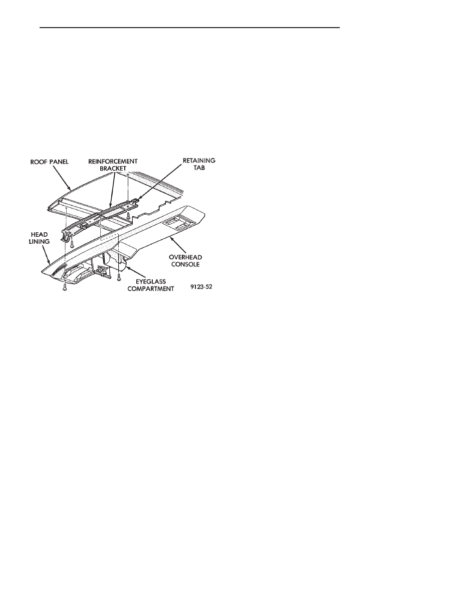
OVERHEAD CONSOLE
REMOVAL (FIG. 33)
(1) Remove screws holding overhead console to re-
inforcement bracket.
(2) Slide overhead console rearward to separate re-
inforcement bracket retainer tab from console.
(3) Lower console from roof and disconnect wire
connectors.
INSTALLATION
Reverse The preceding operation.
HEAD LINING
REMOVAL
(1) Disconnect battery negative cable.
(2) Pull dome lamp downward to disengage from
retaining ring in head lining. Separate lens from
lamp body and remove bulb. Separate bulb holder
from lamp body. Remove attaching screw holding re-
taining ring to roof bow, if equipped.
(3) Remove screws holding coat hooks to roof above
quarter panels.
(4) Remove roof rail and A-pillar mouldings.
(5) Remove screws holding sun visors to roof
header and disconnect wire connector, if equipped.
Remove inboard sun visor hangers.
(6) Remove overhead console, if equipped.
(7) Pull front reading lamp downward to disengage
from retaining ring in head lining and disconnect
wire connector. Remove screws holding retaining
ring to roof header, if equipped.
(8) Remove pinch welt holding headlining to sun
roof opening, if equipped.
(9) Remove screws holding lift gate opening header
moulding to rear roof header. Separate moulding
from header.
(10) Remove one quarter trim panel as necessary
to clear head lining removal path.
(11) Remove head lining from vehicle.
INSTALLATION
Reverse the preceding operation.
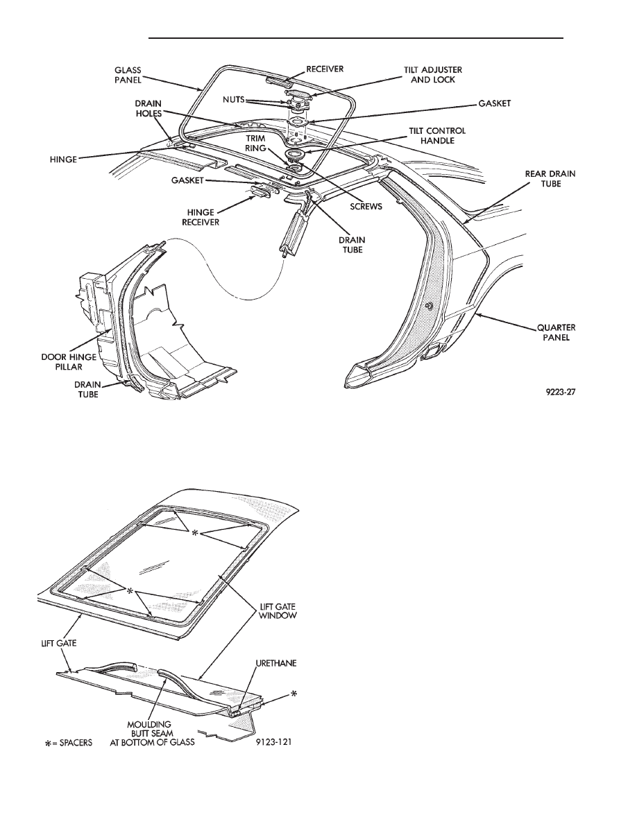
SUNROOF LIFT CONTROL
REMOVAL (FIG. 34)
(1) Remove sunroof glass panel. Refer to Owners
manual for proper procedures.
(2) Remove pinch welt holding head lining to edge
of sunroof opening.
(3) Remove trim ring from tilt control handle.
(4) Remove screws holding tilt control handle to
tilt control. Separate handle from control.
(5) Remove nuts holding lift control to roof panel.
Separate lift control from roof.
INSTALLATION
Reverse the preceding operation.
REAR WINDOW GLASS
The rear window moulding often cannot be sal-
vaged after removal operation is completed. Verify
moulding availability from the parts supplier before
removing moulding.
REMOVAL (FIG. 35)
(1) Remove rear window moulding.
(2) Remove lift gate trim as necessary to gain ac-
cess to rear window defogger wire connector and
ground screw, if equipped.
WARNING: WEAR EYE AND HAND PROTECTION
WHEN HANDLING SAFETY GLASS. PERSONAL IN-
JURY CAN RESULT.
CAUTION: Do not damage body or trim finish when
cutting out glass or applying fence primer.
(3) Cut the urethane around the perimeter of the
back window glass. Refer to Windshield section of
this group for proper procedures.
(4) Separate the rear window from the vehicle.
INSTALLATION
(1) Prepare the work area, window fence, and glass
the same way as described in the Windshield section
of this group.
(2) Place the fence spacers at the locations shown
(Fig. 35).
(3) Apply a 10 mm (0.4 in.) bead of urethane
around the perimeter of the glass.
(4) Install the glass in the same manner described
in the Windshield section of this group.
(5) Install the rear window moulding. Apply 50
mm (2 in.) masking tape over moulding to assure
alignment.
(6) Connect rear window defogger wiring and in-
stall lift gate trim.
Fig. 33 Overhead Console—Typical
Ä
AG-BODY
23 - 65
(7) After urethane has cured remove masking tape
and water test to verify repair. Verify rear window
defogger operation, refer to Group 8N, Rear Window
Defogger.
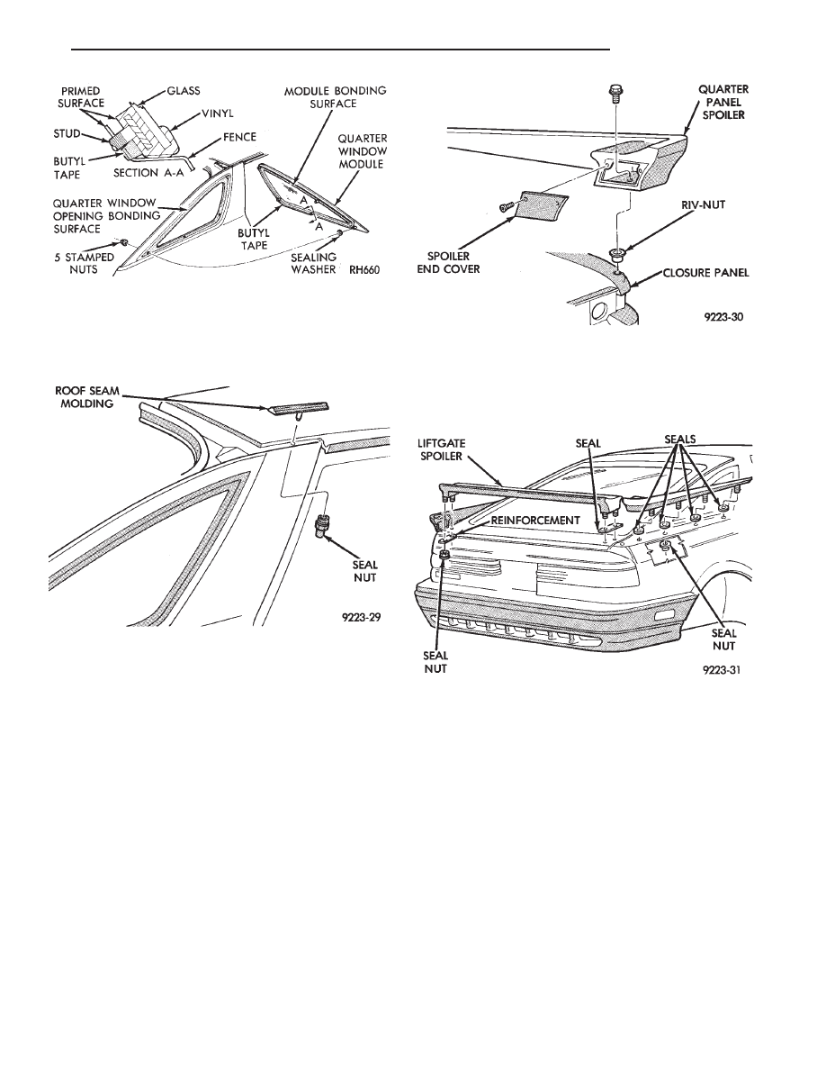
QUARTER GLASS MODULE
REMOVAL (FIG. 36)
(1) Remove quarter trim panel as necessary to
gain access to quarter glass module.
(2) Remove nuts holding quarter glass module to
quarter glass opening.
(3) Cut urethane bonding around perimeter of
quarter glass opening fence.
(4) Push quarter glass module from quarter glass
opening.
(5) Separate module from vehicle.
INSTALLATION
(1) Clean hardened urethane from quarter glass
opening fence and glass module, if module replace-
ment is not required.
(2) Prepare fence and module using method de-
scribed in the Windshield section of this group.
(3) Reverse the removal operation.
ROOF SEAM MOLDING
REMOVAL (FIG. 37)
(1) Remove upper quarter trim panel.
(2) Remove head lining as necessary to gain access
to inside roof panel.
(3) Remove seal nut holding seam molding to roof
panel.
Fig. 34 Sunroof
Fig. 35 Lift Gate Window Glass
23 - 66
AG-BODY
Ä
(4) Separate molding from roof panel.
INSTALLATION
Reverse the preceding operation.
QUARTER PANEL SPOILER
REMOVAL (FIG. 38)
(1) Remove access cover from lift gate opening end
of quarter panel spoiler.
(2) Remove bolt holding spoiler to tail lamp closure
panel.
(3) Remove quarter trim panel.
(4) Remove nuts holding spoiler to quarter panel
from behind quarter panel above rear wheelhouse
(Fig. 38).
(5) Separate spoiler from vehicle.
INSTALLATION
Reverse the preceding operation.
LIFT GATE SPOILER
REMOVAL (FIG. 39)
(1) Raise lift gate to the up position.
(2) Remove nuts holding spoiler to outboard pinch
flanges of lift gate.
(3) Separate spoiler from lift gate.
INSTALLATION
Reverse the preceding operation.
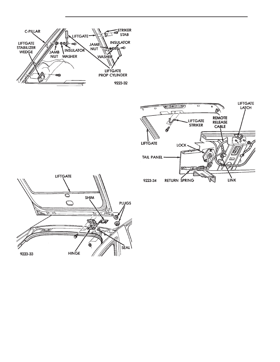
LIFT GATE PROP CYLINDER
REMOVAL (FIG. 40)
(1) raise lift gate to the full open position.
(2) Support lift gate on a suitable lifting device.
(3) Remove bolt holding bottom of lift gate prop
cylinder to c-pillar.
(4) Remove bolt holding top of lift gate prop cylin-
der to lift gate.
(5) Separate prop cylinder from vehicle.
INSTALLATION
Reverse the preceding operation.
LIFT GATE
REMOVAL (FIG. 41)
(1) Raise lift gate to the full open position.
(2) Remove rear roof header molding.
Fig. 36 Quarter Glass Module
Fig. 37 Roof Seam Molding
Fig. 38 Quarter Panel Spoiler
Fig. 39 Lift Gate Spoiler
Ä
AG-BODY
23 - 67
(3) Disconnect lift gate wire connectors and rear
window washer hose, if equipped.
(4) Remove upper lift gate trim molding.
(5) Support lift gate on a suitable lifting device.
(6) Disconnect top of prop cylinders from lift gate.
(7) Mark lift gate hinge locations to assist instal-
lation an alignment of lift gate.
(8) With assistance of a helper, remove bolts hold-
ing lift gate to hinge.
(9) Separate lift gate from vehicle.
INSTALLATION
Reverse the preceding operation.
LIFT GATE LATCH AND STRIKER
LIFT GATE LATCH REMOVAL (FIG. 42)
(1) Raise lift gate to the full open position.
(2) Remove luggage compartment tail trim panel.
(3) Disconnect lock linkage rod from lift gate latch
arm.
(4) Remove nuts holding lift gate latch to tail
panel.
(5) Separate latch from tail panel and disconnect
lift gate remote release cable.
LIFT GATE LATCH INSTALLATION
LIFT GATE STRIKER REMOVAL (FIG. 42)
(1) Raise lift gate to the full open position.
(2) Remove lower lift gate trim panel.
(3) Mark lift gate striker location to assist instal-
lation.
(4) Remove bolts holding lift gate striker to lift
gate.
(5) Separate striker from lift gate.
LIFT GATE STRIKER INSTALLATION
Reverse the preceding operation.
LIFT GATE LOCK CYLINDER
REMOVAL (FIG. 43)
(1) Raise lift gate to the full open position.
(2) Remove luggage compartment tail trim panel.
(3) Disconnect linkage return spring (Fig. 42).
(4) Disconnect linkage rod from lift gate lock arm.
(5) Remove bolts holding lift gate lock to tail
panel.
(6) Separate lock from tail panel.
INSTALLATION
Reverse the preceding operation.
FUEL FILL DOOR
REMOVAL (FIG. 44)
(1) Remove right lower quarter trim panel.
(2) Open fuel fill door.
(3) Remove nuts holding fuel fill door to quarter
panel from in luggage compartment.
(4) Separate fuel fill door from vehicle.
INSTALLATION
Reverse the preceding operation
Fig. 40 Lift Gate Prop Cylinder
Fig. 41 Lift Gate
Fig. 42 Lift Gate Latch and Striker
23 - 68
AG-BODY
Ä
Нет комментариевНе стесняйтесь поделиться с нами вашим ценным мнением.
Текст