Chrysler Le Baron, Dodge Dynasty, Plymouth Acclaim. Manual — part 163
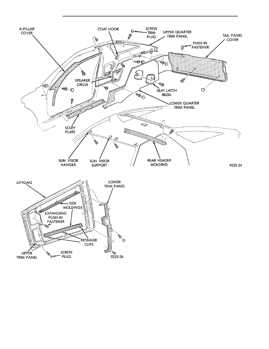
DOOR OPENING SCUFF PLATES
REMOVAL (FIG. 24)
(1) Open front door.
(2) Remove screws holding scuff plate to door sill.
(3) Separate scuff plate from vehicle.
INSTALLATION
Reverse the preceding operation.
A-PILLAR AND ROOF RAIL MOULDINGS
A-PILLAR MOULDING REMOVAL (FIG. 24)
(1) Open front door.
(2) Remove
push-in
fasteners
holding
A-pillar
moulding to roof rail above door opening.
(3) Remove trim plug and screw holding A-pillar
molding to A-pillar
(4) Slide A-pillar moulding upward and pull rear-
ward to separate moulding from A-pillar.
A-PILLAR MOULDING INSTALLATION
Reverse the preceding operation.
LOWER QUARTER TRIM PANEL
REMOVAL (FIG. 24)
(1) Remove tail panel trim cover and security
shade, if equipped
(2) Remove rear seat cushion and backs.
(3) Remove seat back latch striker bezel.
(4) Remove screw covers. Remove screws holding
lower quarter trim panel to quarter.
(5) Pull rearward end of trim panel away from
quarter panel and push trim forward to clear door
opening flange.
(6) Separate lower quarter trim panel from vehicle.
INSTALLATION
Reverse the preceding operation.
UPPER QUARTER TRIM PANEL
REMOVAL (FIG. 24)
(1) Remove lower quarter trim panel.
(2) Remove rear seat shoulder harness turning
loop cover.
(3) Remove bolt holding belt turning loop to C-pil-
lar.
(4) Remove bolt holding front seat belt to floor at
door sill.
(5) Remove screw holding coat hook to roof rail.
(6) Remove roof rail moulding as necessary to clear
quarter panel removal path.
(7) Remove push-in fastener holding upper quarter
trim to roof rail.
(8) Remove screw covers from trim panel to gain
access to screws.
(9) Remove screws holding upper quarter trim to
quarter panel.
(10) Raise and support lift gate in the up position.
Disconnect bottom of lift cylinder.
(11) Swing rear of trim panel away from quarter
panel and pull trim forward to clear door opening
flange.
(12) Separate upper quarter trim panel from vehi-
cle.
INSTALLATION
Reverse the preceding operation.
LOWER TAIL PANEL TRIM COVER
REMOVAL (FIG. 24)
(1) Raise lift gate to the up position.
(2) Remove hidden screws holding tail panel trim
cover to tail panel from carpeted area.
(3) Remove push-in fasteners holding top tail panel
trim to opening sill.
(4) Lift up floor cover and position cover out of the
way.
(5) Separate cover from vehicle.
INSTALLATION
Reverse the preceding operation.
LIFT GATE TRIM
REMOVAL (FIG. 25)
(1) Raise the lift to the up position.
(2) Disengage clips holding side moldings to lift
gate. Separate moldings from lift gate.
(3) Remove expanding push-in fasteners holding
upper trim panel to lift gate.
(4) Remove screw plugs and screws holding upper
trim panel to lift gate. Separate upper trim panel
from lift gate.
(5) Remove screw plug and screw holding lower
trim panel to rear window wiper motor, if equipped.
(6) Remove screws holding lower trim panel to lift
gate. Separate lower trim panel from lift gate.
INSTALLATION
Reverse the preceding operation.
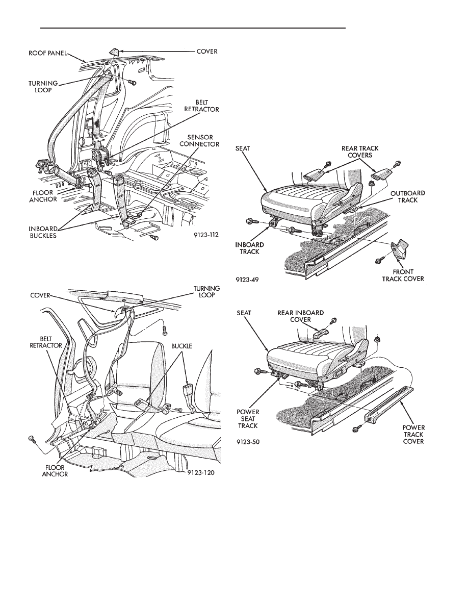
FRONT SEAT BELTS
OUTBOARD SHOULDER HARNESS/LAP BELT
REMOVAL (FIG. 26)
(1) Adjust front seat to the forward position.
(2) Remove bolt holding outboard lap belt anchor
to floor below door sill.
(3) Remove lower and upper quarter trim panels as
necessary to gain access to shoulder harness turning
loop and retractor.
(4) Remove bolt holding shoulder turning loop to
B-pillar.
Ä
AG-BODY
23 - 61
(5) Remove bolt holding belt retractor to quarter
panel.
(6) Separate belt from vehicle.
OUTBOARD SHOULDER HARNESS/LAP BELT
INSTALLATION
Reverse the preceding operation.
INBOARD BUCKLE REMOVAL (FIG. 26)
(1) Remove bolt holding inboard buckle to floor.
(2) Disconnect seat belt sensor wire connector, if
equipped.
(3) Separate buckle assembly from vehicle.
INBOARD BUCKLE INSTALLATION
Reverse the preceding operation.
REAR SEAT BELTS
REAR OUTBOARD SHOULDER HARNESS/LAP
BELT REMOVAL (FIG. 27)
(1) Remove lower and upper quarter trim panel.
(2) Remove bolt holding lap belt anchor to floor at
wheelhouse kickup.
(3) Remove bolt holding seat belt retractor to quar-
ter panel.
REAR OUTBOARD SHOULDER HARNESS/LAP
BELT INSTALLATION
Reverse the preceding operation.
REAR INBOARD BUCKLE REMOVAL (FIG. 27)
(1) Lift seat belt buckle anchor cover to expose
bolt.
(2) Remove bolt holding inboard buckle/center oc-
cupant belt to seat frame.
(3) Separate buckle from vehicle.
Fig. 24 Interior Mouldings, Panels, and Trim Covers
Fig. 25 Lift Gate Trim
23 - 62
AG-BODY
Ä
REAR INBOARD BUCKLE INSTALLATION
Reverse the preceding operation.
FRONT SEATS
REMOVAL (FIG. 28 OR 29)
(1) Position seat full forward.
(2) Remove screws holding rear track riser covers
and separate covers from tracks.
(3) On power seat track, remove outboard track
cover.
(4) Remove nuts holding seat track to floor.
(5) Position seat full rearward.
(6) On power seat track, remove door sill scuff
plate and disconnect wire connector.
(7) Remove bolts holding seat track to cross mem-
ber.
(8) Remove seat from vehicle.
INSTALLATION
Reverse the preceding operation.
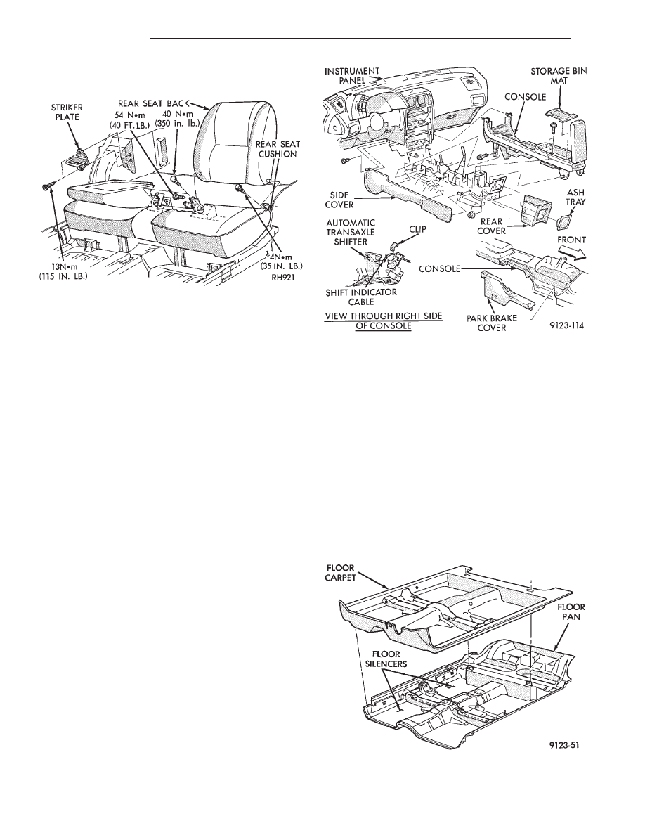
REAR SEATS
REMOVAL (FIG. 30)
(1) Hinge seat backs forward.
(2) Remove bolts holding rear seat frame to floor
on sides of center floor hump near luggage compart-
ment kick-up.
(3) Pull seat forward to disengage retaining hooks
from floor.
(4) Separate seat from vehicle.
Fig. 26 Front Seat Belts—Typical
Fig. 27 Rear Seat Belts
Fig. 28 Manual Front Seat
Fig. 29 Power Front Seat
Ä
AG-BODY
23 - 63
INSTALLATION
Reverse the preceding operation.
FRONT CENTER CONSOLE
REMOVAL (FIG. 31)
(1) Position front seats full forward.
(2) Remove rear ash tray.
(3) Remove rear lower carpeted end cover.
(4) Remove nuts holding console to floor bracket.
(5) Position front seats full rearward.
(6) Raise console storage bin cover and remove bot-
tom mat.
(7) Remove screws holding bottom of storage bin to
floor bracket.
(8) Remove screws holding console side panels to
instrument panel. Disengage hook and loop fasteners
and separate side panels from console.
(9) Disconnect shift indicator cable and clips from
shift mechanism through right side panel opening, if
equipped with automatic transaxle. Refer to Group
8E, Instrument Panel and Gauges for proper proce-
dures.
(10) Disengage clips holding parking brake lever
cover to console and separate cover from vehicle.
(11) Remove center instrument panel bezel. Refer
to Group 8E, Instrument Panel. Remove screws hold-
ing console to instrument panel.
(12) Remove screws holding console to lower in-
strument panel.
(13) Remove bolts holding console to forward floor
mounting bracket.
(14) Remove gear selector knob.
(15) Separate console from floor and remove from
vehicle.
INSTALLATION
Reverse the preceding operation.
FLOOR CARPET
REMOVAL (FIG. 32)
(1) Remove cowl trim panels and scuff plates.
(2) Remove front seats and inboard seat belts.
(3) Remove center arm rest and front console.
(4) Remove inboard and outboard seat belt lower
attaching bolts.
(5) Remove left dash panel foot rest.
(6) Remove rear seat.
(7) Pull carpet from under quarter trim covers.
(8) Fold carpet and remove through door opening.
INSTALLATION
Reverse the preceding operation.
Fig. 30 Rear Seat Cushion and Back
Fig. 31 Center Console
Fig. 32 Floor Carpet and Silencers—Typical
23 - 64
AG-BODY
Ä
Нет комментариевНе стесняйтесь поделиться с нами вашим ценным мнением.
Текст