Chrysler Le Baron, Dodge Dynasty, Plymouth Acclaim. Manual — part 227
WARNING: THE SELF ADJUSTING FEATURE OF THIS
PARKING BRAKE LEVER ASSEMBLY CONTAINS A
CLOCK SPRING LOADED TO APPROXIMATELY 30
POUNDS. CARE MUST BE TAKEN TO PREVENT EX-
CESSIVE JARRING OF THE ASSEMBLY. DO NOT
RELEASE THE SELF ADJUSTER LOCKOUT DEVICE
BEFORE INSTALLING CABLES INTO THE EQUAL-
IZER. KEEP HANDS OUT OF SELF ADJUSTER SEC-
TOR AND PAWL AREA. FAILURE TO OBSERVE CAU-
TION IN HANDLING THIS MECHANISM COULD LEAD
TO SERIOUS INJURY.
When repairs to the hand lever assembly or cable
system are required the self adjuster must be reloaded
and locked out.
SELF ADJUSTING PROCEDURES (AG & AJ BODY)
TO RELOAD SELF ADJUSTER
(1) Remove ash receiver or courtesy light from rear
of center console to gain access to self adjuster. Also,
remove carpet from sides of console.
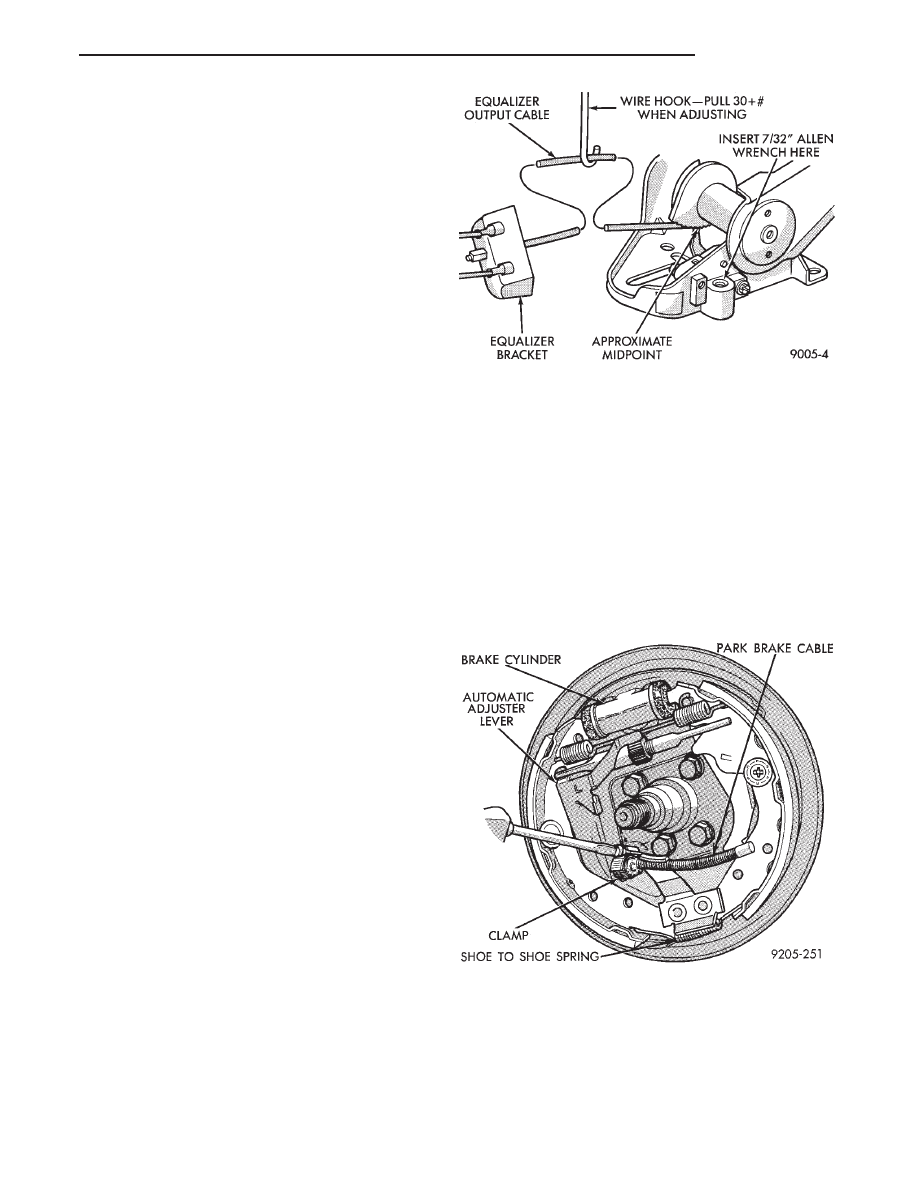
(2) Pull on equalizer/output cable to wind up sprin-
g(requires greater than 30 pounds effort). Continue
until self adjuster lockout pawl is positioned about
midway on the self adjuster sector (Fig. 6). Rotate
lockout pawl into self adjuster sector by turning allen
screw clockwise. Rotating lockout device requires
very little effort. Do not force or failure of lock-
out device will occur.
(3) When repairs are complete, adjust rear brakes
before adjusting parking brake. On drum-in-hat type of
rear disc brake adjust shoe diameter to 171.5 mm (6.75
inch).
ADJUST PARKING BRAKE (AG & AJ BODY)
Be sure that the cables are properly assembled to the
equalizer bracket prior to cable adjustment.
(1) Insert a 7/32 inch allen wrench into hex socket
and turn counter-clockwise through approximately 15°
of rotation (Fig. 4). In turning lockout device, self
adjuster release is a loud snapping noise followed by
reaching a more felt than heard detent. Very light
effort is required to seat lockout arm into detent.
Follow through to the detent is important in prevent-
ing the lockout rod from rattling.
Note: The parking brake handle can be in any
position when releasing self adjuster.
(2) Cycle lever to position cables. Rear wheels should
rotate freely without dragging.
REAR PARKING BRAKE CABLE REMOVAL (AA, AC,
AP, AY BODY)
The rear brake cables are attached to rear connec-
tors.
Should it become necessary to remove either parking
brake cable for installation of a new cable, proceed as
follows:
With vehicle jacked up on a suitable hoist, remove
wheel and tire assembly (Fig. 6).
Back off cable adjusting nut to provide slack and
disconnect rear brake cable from connector.
DRUM BRAKES
(1) Disconnect park brake cable from park brake
lever in rear wheel brakes.
(2) Using an aircraft type hose clamp compress re-
tainers on end of cable housing and start cable out of
retaining hole in the support plate. Remove clamp
when retainers are free of the mounting hole in the
support plate, (Fig. 6).
(3) Remove clip from brake cable at support
bracket and pull cable away from trailing arm as-
sembly (Figs. 3 and 4).
DISC BRAKES
(1) Remove disc brake caliper from adapter, and
brake disc (rotor) from rear hub.
Fig. 5 Self Adjusting Parking Brake Lever Assembly
Fig. 6 Removing Brake Cable from Support Plate
Ä
BRAKES
5 - 61
(2) Disconnect parking brake cable from brake
shoe lever.
(3) Using an aircraft type hose clamp compress re-
tainers on end of cable housing and start cable out of
retaining hole in the adapter. Remove clamp when
retainers are free of mounting hole in the adapter
(Fig. 6).
(4) Remove clip from parking brake cable at
hanger bracket and pull cable away from trailing
arm.
REAR PARKING BRAKE CABLE INSTALLATION
DRUM BRAKES (AA, AC, AP, AY BODY)
(1) Route parking brake cable assembly through
trailing arm and hanger bracket.
(2) Install parking brake cable retaining clip.
(3) Install parking brake cable into rear brake sup-
port plate. Be sure all retainers are expanded around
mounting hole in brake support plate, and then con-
nect parking brake cable end to brake shoe lever.
(4) Insert forward end of parking brake cable into
connector.
(5) Install brake drum, and wheel and tire assem-
bly.
DRUM BRAKES (AG & AJ BODY)
(1) Route each parking brake cable assembly
through trailing arm and mounting bracket.
(2) Install parking brake cable retaining clip.
(3) Install parking brake cable into rear brake sup-
port plate. Be sure the retainers are expanded
around mounting hole in the brake support plate and
connect parking brake cable end to brake shoe lever.
(4) Insert forward end of parking brake cable into
floor pan of vehicle. Then connector park brake cable
to equalizer at park brake hand lever.
(5) Install brake drum, and wheel and tire assem-
bly.
DISC BRAKES (AA, AC, AP, AY BODY)
(1) Route parking brake cable assembly through
trailing
arm
and
parking
brake
cable
hanger
bracket.
(2) Install parking brake cable to hanger bracket
retaining clip.
(3) Install parking brake cable into rear brake
adapter. Be sure all cable retainers on parking brake
cable are expanded around mounting hole in adapter
and connect cable end to brake shoe lever.
(4) Insert forward end of cable into connector.
(5) Adjust parking brake shoe diameter to 171 mm
(6.75 inch).
(6) Install rear braking disc, caliper assembly and
wheel and tire assembly.
DISC BRAKES (AG & AJ BODY)
(1) Route each individual parking brake cable as-
sembly through trailing arm and parking brake ca-
ble mounting bracket.
(2) Install
parking
brake
cable
to
mounting
bracket retaining clip.
(3) Install parking brake cable into rear disc brake
adapter. Be sure all cable retainers on parking brake
cable are expanded around mounting hole in adapter,
and then connect cable end to brake shoe lever.
(4) Insert forward end of parking brake cable into
floor pan of vehicle. Then connector park brake cable
to equalizer at park brake hand lever.
(5) Adjust parking brake shoe diameter to 171 mm
(6.75 inch).
(6) Install rear braking disc, caliper assembly and
wheel and tire assembly.
REMOVING PARKING BRAKE FRONT CABLE (AA,
AC, AP, AY BODY)
(1) Loosen parking brake cable adjusting nut un-
der car. Disengage front cable from intermediate ca-
ble connector (Fig. 2).
(2) Remove park brake cable retaining clip from
floor pan of vehicle.
(3) Lift floor mat for access to floor pan.
(4) Remove floor pan seal.
(5) Pull parking brake cable strand end forward
and disconnect from foot lever clevis. Separate park-
ing brake cable from parking brake foot lever and
bracket on body rail.
(6) Pull parking brake cable assembly through
hole in floor pan and up into vehicle.
INSTALLING PARKING BRAKE FRONT CABLE (AA,
AC, AP AY Body)
(1) Insert parking brake cable housing retainers
into hole in rail bracket and parking brake foot lever
assembly (Fig. 2).
(2) Feed parking brake cable end through holes in
floor pan and rail bracket, from the interior of the
vehicle.
(3) Install floor pan seal.
(4) Engage parking brake cable strand end in foot
lever clevis. Seat cable ends in parking brake assem-
bly and parking brake cable rail bracket.
(5) Replace floor mat.
(6) Attach park brake cable retaining clip to floor
pan of vehicle.
(7) Engage rear parking brake cable end to inter-
mediate cable connector.
(8) Adjust service and parking brakes.
5 - 62
BRAKES
Ä
PARKING BRAKE HAND LEVER ASSEMBLY
REMOVAL AND INSTALLATION
REMOVAL (AG AND AJ BODY)
Remove ash receiver or courtesy light from rear of
console. Remove carpet from sides of console. Remove
parking brake trim cover from passenger side of con-
sole (pulls off).
Load and lockout parking brake self adjuster (Fig.
6). Disconnect rear cables from equalizer bracket.
Remove the 3 hold down nuts and remove hand le-
ver assembly through opening created by removing
console trim cover. Passenger seat might have to be
removed. Also, if metal tab at bottom of console pre-
vents removal of hand brake assembly, bend tab out
of the way. (Bend the tab back to original position af-
ter R & R of hand brake).
INSTALLATION (AG AND AJ BODY)
Install hand lever assembly through side opening
in console and bolt into place.
Connect rear parking brake cables to equalizer.
Adjust parking brakes.
Install console trim cover, carpet, passenger seat
and rear ash receiver or courtesy light.
REMOVAL AND INSTALLATION PARKING BRAKE
SHOES
ALL WITH REAR DISK BRAKES
(1) Remove rear disc brake caliper assembly from
adapter and braking disc (See Disc Brake Shoe Re-
moval).
(2) Remove rear braking disc from rear hub (See
Removing Braking Disk).
(3) Remove grease cap.
(4) Remove cotter pin, lock nut, hub bearing re-
taining nut, and washer.
(5) Remove hub and bearings.(See Wheel Bearing
Section)
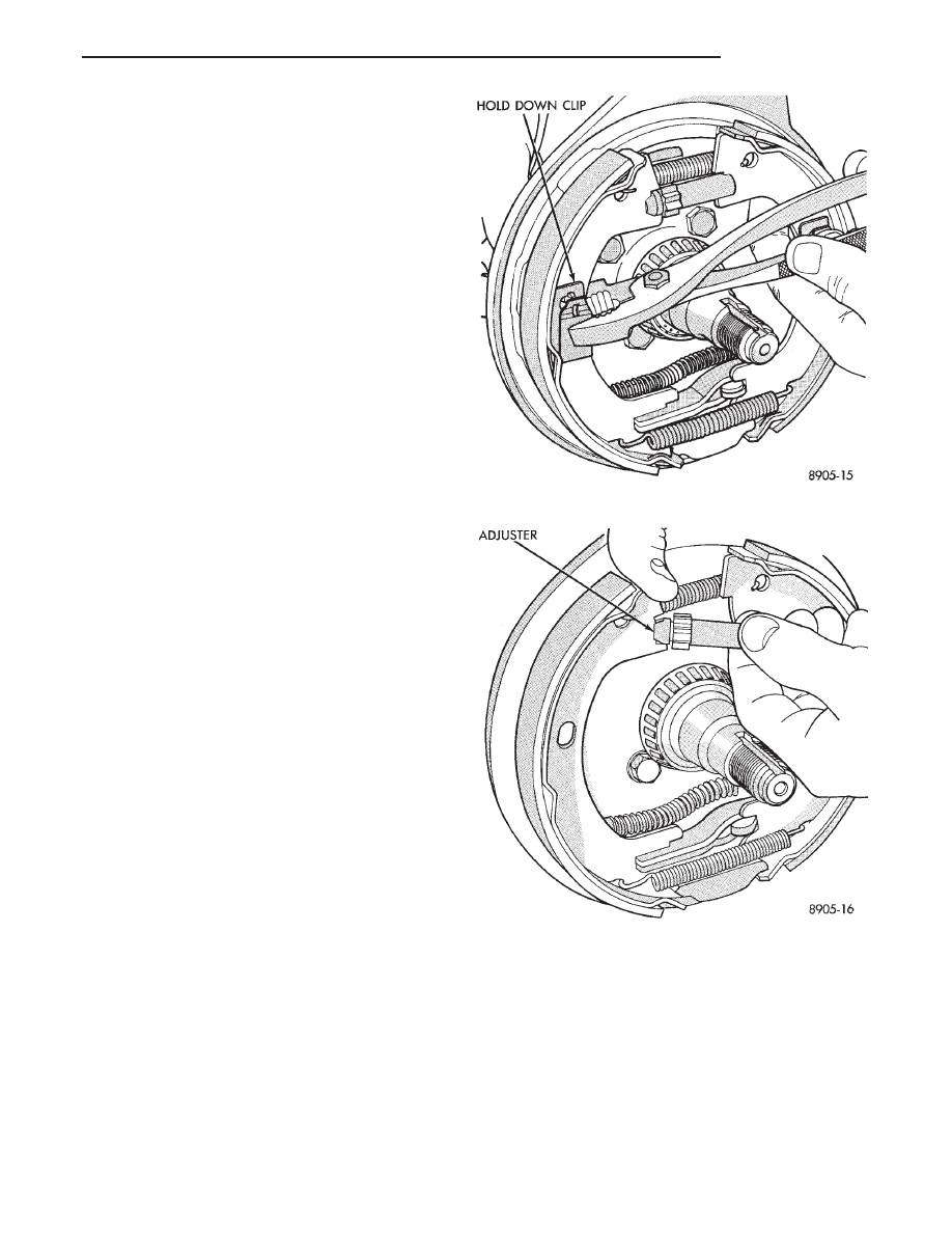
(6) Remove forward brake shoe assembly hold
down clip (Fig. 1).
(7) Turn parking brake, brake shoe adjuster wheel
until adjuster is at shortest length.
(8) Remove the parking brake, shoe adjuster as-
sembly (Fig. 2).
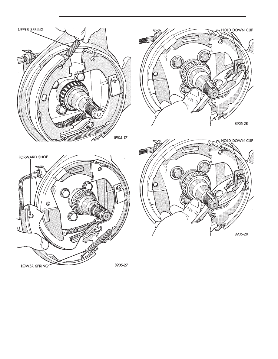
(9) Remove upper parking brake, shoe to shoe
spring (Fig. 3).
(10) Pull front parking brake shoe, away from an-
chor. Then remove front parking brake shoe and
lower spring (Fig. 4).
(11) Remove rear parking brake shoe hold-down
clip. Then remove rear parking brake shoe assembly
(Fig. 5).
Fig. 1 Removing Brake Shoe Hold-Down Clip
Fig. 2 Removing Adjuster Assembly
Ä
BRAKES
5 - 63
INSTALLING PARKING BRAKE SHOES
(1) Install rear parking brake shoe and holddown
clip (Fig. 6).
(2) Install lower parking brake, shoe to shoe re-
turn spring (Fig. 7).
(3) Pull forward parking brake shoe over anchor
block until properly located on adapter.
(4) Install upper parking brake, shoe to shoe re-
turn spring (Fig. 8).
(5) Install parking brake shoe adjuster assembly
with star wheel forward (Fig. 9).
(6) Install front, parking brake shoe holddown clip
(Fig. 10).
(7) Adjust parking brake shoes to a diameter to
171 mm (6.75 inch).
(8) Install hub assembly on spindle.
(9) Install outer bearing, thrust washer and nut.
(10) Tighten wheel bearing adjusting nut to 27 to
34 N
Im (240 to 300 in. lbs.) torque while rotating
hub. This seats the bearings.
(11) Back off adjusting nut 1/4 turn (90°) then
tighten adjusting nut finger tight.
(12) Position lock on nut with one pair of slots in
line with cotter pin hole. Install cotter pin.
(13) Install grease cap.
(14) Install rear braking disc.
(15) Install rear, disc brake caliper on the adapter
(See Brake Shoe Removal).
Fig. 3 Removing Upper Spring
Fig. 4 Removing Shoe and Lower Spring
Fig. 5 Removing Rear Holddown Clip and Shoe
Fig. 6 Installing Rear Shoe and Hold-Down Clip
5 - 64
BRAKES
Ä
Нет комментариевНе стесняйтесь поделиться с нами вашим ценным мнением.
Текст