Chrysler Le Baron, Dodge Dynasty, Plymouth Acclaim. Manual — part 182
(6) Disengage frog-leg fasteners holding trim panel
to inner door panel.
(7) Lift trim panel upward and separate trim from
door.
(8) Disconnect courtesy lamp, power door lock
switch and power window switch wire connectors.
TRIM PANEL INSTALLATION
Reverse the preceding operation.
SIDE VIEW MIRROR TRIM COVER
REMOVAL
(1) Remove Front door trim panel.
(2) Disconnect power mirror wire connector.
(3) Remove screws holding mirror trim cover to
door frame.
INSTALLATION
Reverse the preceding operation.
DOOR FRAME TRIM MOULDING
REMOVAL (FIG. 11)
(1) Remove front door trim panel.
(2) Disengage trim clips holding moulding to win-
dow opening frame and separate moulding from door.
INSTALLATION
Reverse the preceding operation.
FRONT DOOR SILENCER AND WATER SHIELD
REMOVAL
(1) Remove front door trim panel.
(2) Pull water shield from adhesive around perim-
eter of door inner panel.
INSTALLATION
Reverse the preceding operation.
FRONT DOOR AND HINGE
The front door hinge is welded to the door and
bolted to the hinge pillar. The door half of the hinge
pivots on a removable hinge pin. The hinge pin is
driven in from the bottom on the top hinge and from
the top on the bottom hinge. All adjustments to the
hinge are performed on the hinge pillar half of the
hinge. If the welded half of the hinge must be bent to
align door, consult an authorized body repair facility.
FRONT DOOR REMOVAL (FIG. 12)
(1) Remove door trim panel, silencer pad, and wa-
ter shield.
(2) Disconnect all wire connectors and wire har-
ness hold downs inside door and push wire harness
through access hole in front of door into hinge pillar
opening.
(3) Open door and support door on a suitable lift-
ing device.
(4) Drive bottom hinge pin upward and remove pin
from hinge.
(5) Drive top hinge pin downward and remove pin
from hinge.
FRONT DOOR INSTALLATION
Reverse the preceding operation. The door should
not require re-alignment. If door does need align-
ment, refer to Front Door Hinge Installation para-
graph in this section.
FRONT DOOR HINGE REMOVAL (FIG. 12)
(1) Remove front fender wheelhouse splash shield.
Refer to Front Wheelhouse Splash Shield Removal
paragraph in this section.
(2) Support door on a suitable lifting device.
(3) Drive out hinge pin on the effected hinge.
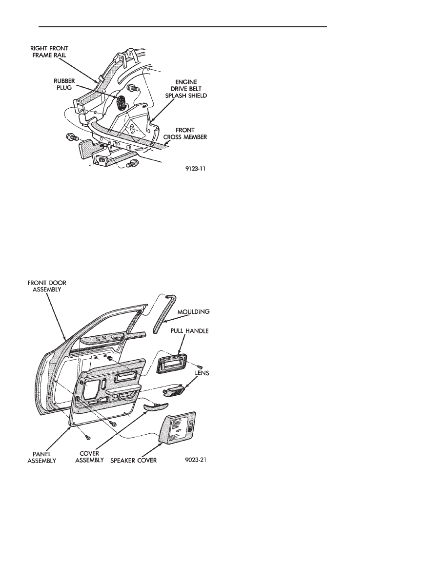
Fig. 10 Engine Drive Belt Splash Shield—Typical
Fig. 11 Front Door Trim Panel
Ä
AY-BODY
23 - 137
(4) Remove bolts holding hinge to hinge pillar and
separate hinge form vehicle.
FRONT DOOR HINGE INSTALLATION
Reverse the preceding operation. Align door to
achieve 6 mm (0.240 in.) gap to all surrounding pan-
els and flush across gaps.
OUTSIDE DOOR HANDLE
REMOVAL (FIG. 13)
(1) Remove door trim panel.
(2) Remove silencer pad and water shield as neces-
sary.
(3) Raise door glass to up position.
(4) Disconnect illuminated entry wire connector
from outside door handle assembly, if equipped.
(5) Disconnect latch release linkage from latch as-
sembly.
(6) Disconnect lock cylinder linkage from latch as-
sembly.
(7) Remove nuts holding outside handle bracket to
door panel and separate bracket from panel.
(8) Position linkage rods parallel to the back of
handle and remove handle assembly from door.
INSTALLATION
Reverse the preceding operation.
FRONT DOOR LATCH
REMOVAL (FIG. 14)
(1) Remove door trim panel.
(2) Remove silencer pad and water shield as neces-
sary.
(3) Disconnect linkage rods from door latch assem-
bly.
(4) Remove screws holding latch door end frame.
(5) Separate latch from door.
INSTALLATION
Reverse the preceding operation.
FRONT DOOR WINDOW REGULATOR
REMOVAL (FIG. 15 OR 16)
MANUAL OR ELECTRIC
(1) Remove front door trim panel.
(2) Remove silencer pad and water shield.
(3) Remove side view mirror trim cover and door
frame trim moulding.
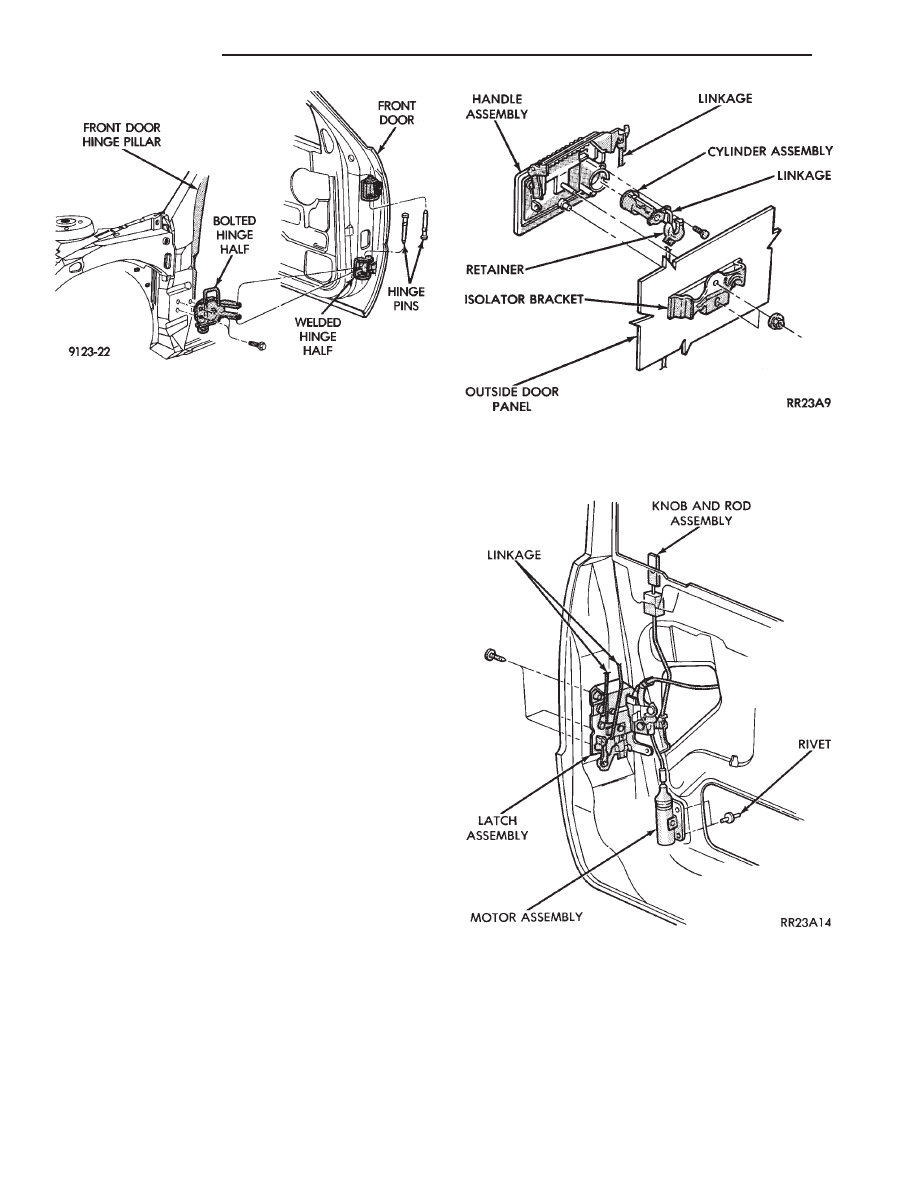
Fig. 12 Front Door Assembly
Fig. 13 Front Door Handle Assembly
Fig. 14 Front Door Latch Assembly
23 - 138
AY-BODY
Ä
(4) Remove door glass.
(5) Remove nut holding cable retainer to inner
door panel and slip cables from behind retainer.
(6) Disengage push in retainer holding cables to
inner door panel above speaker on vehicles with
power windows.
(7) Remove bolts holding top of glass lift bar to in-
ner door panel.
(8) Remove nut holding bottom of lift bar to bot-
tom panel of door.
(9) Remove bolts holding window crank regulator
to inner door panel on vehicles with manual win-
dows. Remove nuts holding motor and regulator to
inner door panel on vehicles with power windows.
(10) Separate window regulator from vehicle.
INSTALLATION
Reverse the preceding operation.
FRONT DOOR GLASS
REMOVAL
(1) Remove front door trim panel.
(2) Remove silencer pad and water shield.
(3) Remove side view mirror trim cover and door
frame trim moulding.
(4) Remove front door speaker.
(5) Move glass to the down position and remove
glass to lift plate fasteners.
(6) Loosen door glass slam bumpers.
(7) Lift glass upward through opening at top of
door.
INSTALLATION
Reverse the preceding operation.
REAR DOOR TRIM PANEL
REMOVAL (FIG. 17)
(1) Remove screw plugs from fixed glass trim be-
zel. Remove screws holding bezel to door frame and
separate trim from door.
(2) Remove screws holding pull handle and padded
insert to door trim and separate handle and insert
from door.
(3) Disengage frog-leg fasteners holding forward
padded insert assembly to door panel.
(4) Remove hidden screws from behind carpeting
on lower trim panel.
(5) Remove screws and disengage frog-leg fasteners
holding trim panel to door. Lift trim panel upward
and separate trim from door.
(6) Disconnect courtesy lamp wire connector. Dis-
connect cigar lighter wire connectors. Disconnect
power window switch wire connector.
INSTALLATION
Reverse the preceding operation.
REAR DOOR FRAME TRIM MOULDING
TRIM MOULDING REMOVAL
(1) Remove rear door trim panel.
(2) Disengage trim clips holding trim moulding to
door frame.
(3) Separate trim moulding from door frame.
TRIM MOULDING INSTALLATION
Reverse the preceding operation.
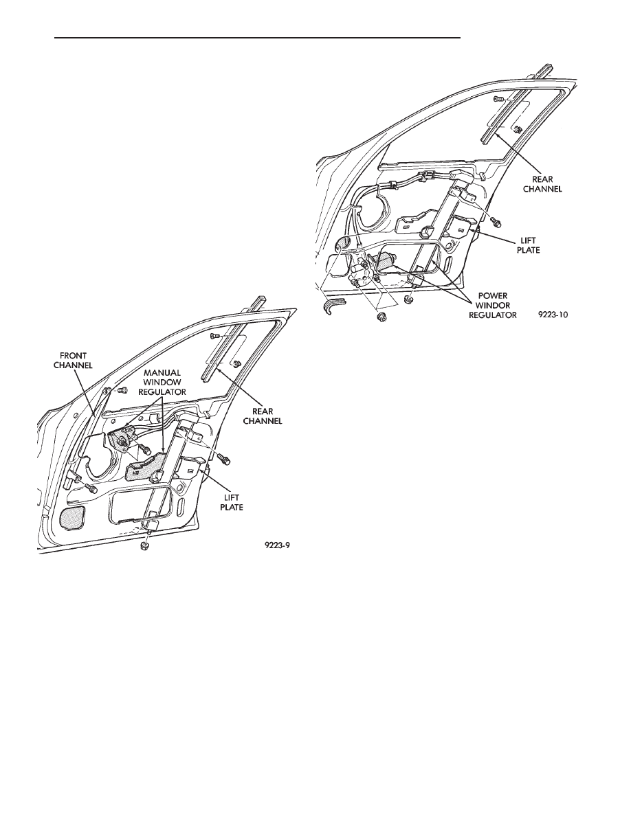
Fig. 15 Front Door Manual Window Regulator
Fig. 16 Front Door Power Window Regulator
Ä
AY-BODY
23 - 139
REAR DOOR SILENCER AND WATER SHIELD
REMOVAL
(1) Remove door trim panel.
(2) Pull water shield from adhesive around perim-
eter of door inner panel.
INSTALLATION
Reverse the preceding operation.
REAR DOOR AND HINGE
The rear door hinge is welded to the door and
bolted to the B-pillar. The door half of the hinge piv-
ots on a removable hinge pin. The hinge pin is
driven in from the bottom on the top hinge and from
the top on the bottom hinge. All adjustments to the
hinge are performed on the hinge pillar half of the
hinge. If the welded half of the hinge must be bent to
align door, consult an authorized body repair facility.
REAR DOOR REMOVAL (FIG. 18)
(1) Remove B-pillar trim panel and disconnect all
wire connectors leading to door. Push wire harness
through access hole in B-pillar into hinge opening.
(2) Support door on a suitable lifting device.
(3) Drive bottom hinge pin upward and remove pin
from hinge.
(4) Drive top hinge pin downward and remove pin
from hinge.
(5) Separate door from vehicle.
REAR DOOR INSTALLATION
Reverse the preceding operation. The door should
not require re-alignment. If door does need align-
ment, refer to Rear Door Hinge Installation para-
graph in this section.
REAR DOOR HINGE REMOVAL (FIG. 18)
(1) To remove upper hinge bolted half, remove
B-pillar trim panel. To remove lower hinge bolted
half it is not necessary to remove B-pillar trim.
(2) Support rear door on a suitable lifting device.
(3) Drive out hinge pin on the effected hinge.
(4) Remove bolts holding hinge to B-pillar and sep-
arate hinge form vehicle.
REAR DOOR HINGE INSTALLATION
Reverse the preceding operation. Align door to
achieve 6 mm (0.240 in.) gap to all surrounding pan-
els and flush across gaps.
REAR DOOR OUTSIDE HANDLE
REMOVAL
(1) Remove rear door trim panel.
(2) Remove silencer pad and water shield as neces-
sary.
(3) Disconnect latch release linkage rod from door
latch.
(4) Remove nuts holding handle bracket to inner
door panel.
(5) Separate outside door handle from door.
INSTALLATION
Reverse the preceding operation.
REAR DOOR LATCH
REMOVAL
(1) Remove rear door trim panel.
(2) Remove silencer pad and water shield as neces-
sary.
(3) Disconnect linkage rods from door latch.
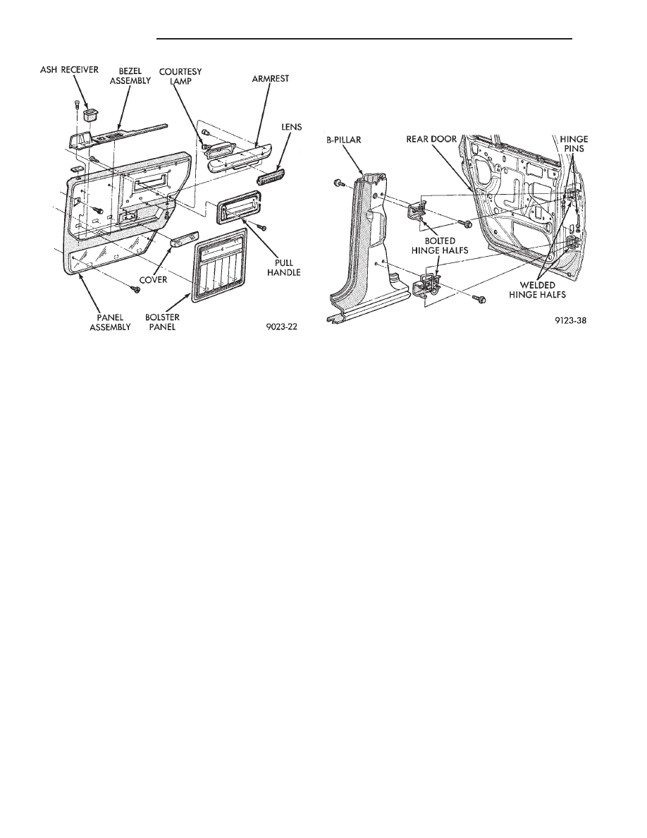
Fig. 17 Rear Door Trim Panel
Fig. 18 Rear Door Assembly—Typical
23 - 140
AY-BODY
Ä
Нет комментариевНе стесняйтесь поделиться с нами вашим ценным мнением.
Текст