Chrysler Le Baron, Dodge Dynasty, Plymouth Acclaim. Manual — part 47

Wastegate Duty Cycle
Battery Temperature
Map Sensor Voltage
Vehicle Speed
Oxygen Sensor State
Baro Read Update
MAP Gauge Reading
Throttle Opening (percentage)
Total Spark Advance
CIRCUIT ACTUATION TEST MODE
The purpose of the circuit actuation test mode is to
check for the proper operation of output circuits or
devices which the powertrain control module (PCM)
cannot internally recognize. The PCM can attempt to
activate these outputs and allow an observer to ver-
ify proper operation. Most of the tests available in
this mode provide an audible or visual indication of
device operation (click of relay contacts, spray fuel,
etc.). With the exception of an intermittent condition,
if a device functions properly during its test, assume
the device, its associated wiring, and its driver cir-
cuit are in working order.
OBTAINING CIRCUIT ACTUATION TEST
Connect the DRBII scan tool to the vehicle and ac-
cess the Actuators screen. The following is a list of
the
engine
control
system
functions
accessible
through Actuators screens.
Stop All Tests
Ignition Coil #1
Ignition Coil #2
Fuel Injector #1
Fuel Injector #2
Fuel Injector #3
Idle Air Control Motor Open/Close
Radiator Fan Relay
A/C Clutch Relay
Auto Shutdown Relay
Purge Solenoid
S/C Serv Solenoids
Generator Field
Tachometer Output
Wastegate Solenoid
Baro Read Solenoid
All Solenoids/Relays
Speed Control Vent Solenoid
Speed Control Vacuum Solenoid
ASD Fuel System Test
Fuel Injector #4
THROTTLE BODY MINIMUM AIR FLOW CHECK
PROCEDURE
(1) Warm the engine in neutral until the cooling
fan has cycled on and off at least once.
(2) Shut off engine.
(3) Hook-up Tachometer.
(4) Disconnect the PCV valve hose from the nipple
on the intake manifold.
(5) Attach air metering fitting, special tool 6457
(0.125 inch orifice), to the intake manifold PCV nip-
ple.
(6) Disconnect 3/16 inch manifold vacuum purge
line from the top of the throttle body. Cap the 3/16
inch throttle body nipple.
(7) Connect DRBII scan tool.
(8) Restart engine. Allow engine to idle for at least
one minute.
(9) Using the DRBII scan tool, access Min. Airflow
Idle Spd. The following will then occur:
• Idle air control motor will fully close.
• Idle spark advance will become fixed.
• Engine RPM will be displayed on the DRBII scan
tool.
(10) Check idle RPM with tachometer, if idle RPM
is within the below specification then the throttle
body minimum airflow is set correctly.
If the idle RPM is not within specification, replace
the throttle body.
(11) Shut off engine.
(12) Remove air metering fitting 6457 from the in-
take manifold PCV nipple. Connect the PCV hose to
the nipple.
(13) Remove DRBII scan tool.
(14) Disconnect tachometer.
(15) Reconnect purge line to throttle body.
IGNITION TIMING PROCEDURE
Ignition timing cannot be changed or set on the
Turbo III engine. Refer to Group 8D for a description
of the Direct Ignition System (DIS).
60-WAY PCM WIRING CONNECTOR
Refer to the PCM wiring connector diagram (Fig.
2) for information regarding wire colors and cavity
numbers.
IDLE SPECIFICATIONS
Ä
FUEL SYSTEMS
14 - 105
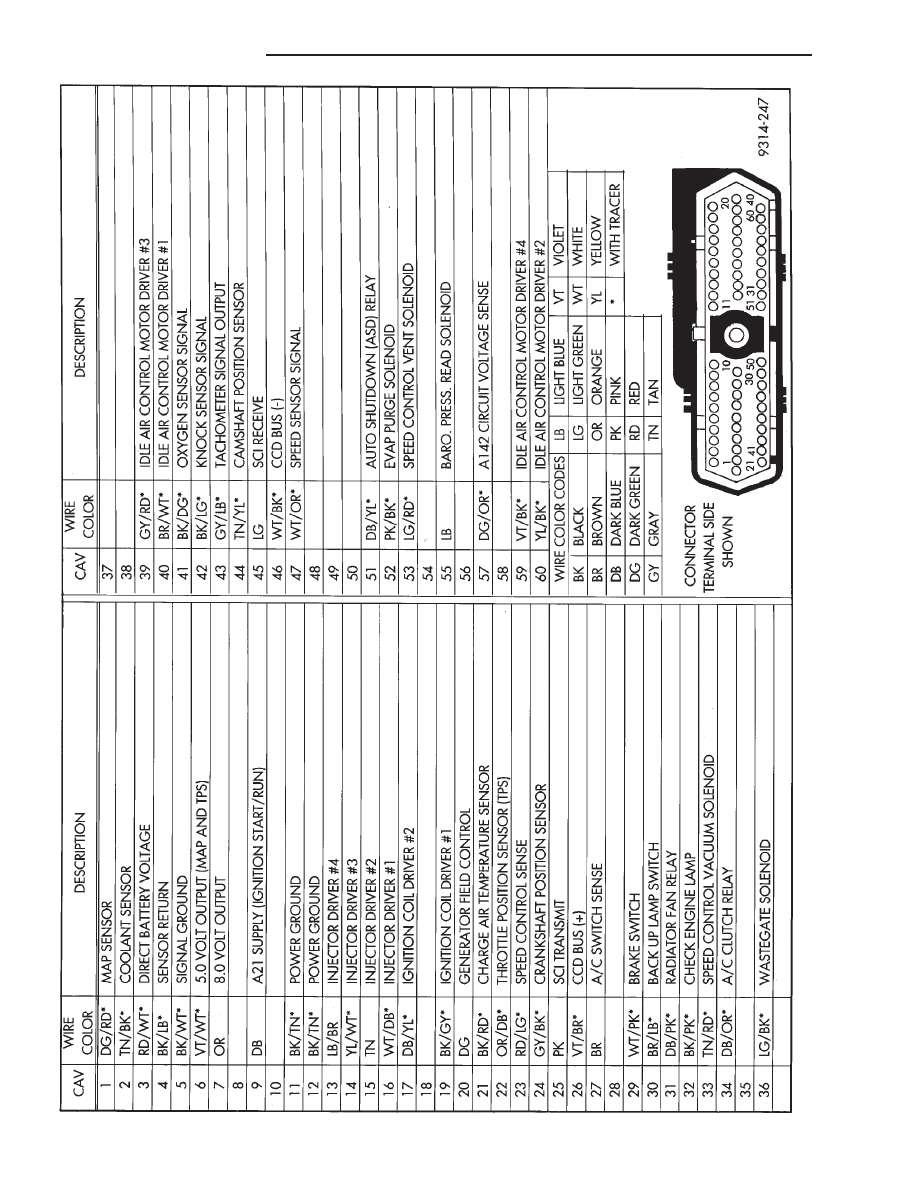
Fig.
2
60-W
ay
PCM
W
iring
Connector
14 - 106
FUEL SYSTEMS
Ä
2.2L TURBO III MULTI-PORT FUEL INJECTION—SERVICE PROCEDURES
INDEX
page
page
Fuel Injector Rail Assembly
. . . . . . . . . . . . . . . . 109
Fuel Injectors
. . . . . . . . . . . . . . . . . . . . . . . . . . 110
Fuel Pressure Regulator
. . . . . . . . . . . . . . . . . . 111
Fuel System Pressure Release Procedure
. . . . . 107
Heated Oxygen Sensor (O
2
Sensor)
. . . . . . . . . 112
Idle Air Control Motor
. . . . . . . . . . . . . . . . . . . . 108
Manifold Absolute Pressure (MAP) Sensor
Service
. . . . . . . . . . . . . . . . . . . . . . . . . . . . . . 111
PCM Service
. . . . . . . . . . . . . . . . . . . . . . . . . . . 111
Throttle Body
. . . . . . . . . . . . . . . . . . . . . . . . . . . 107
Throttle Body Removal
. . . . . . . . . . . . . . . . . . . 108
Throttle Position Sensor (TPS)
. . . . . . . . . . . . . 107
Wastegate and Canister Purge Solenoid Service . 111
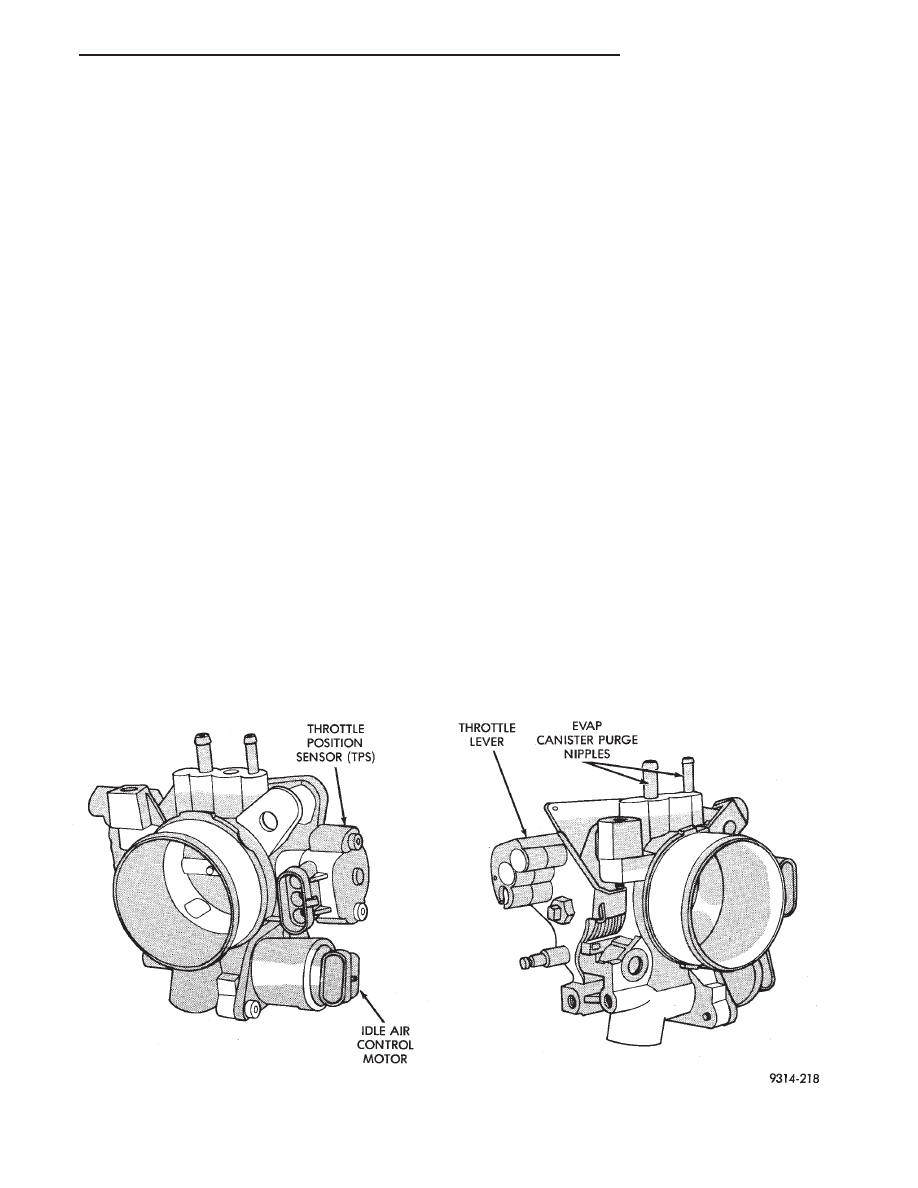
THROTTLE BODY
When servicing throttle body components, always
reassemble components with new O-rings and seals
where applicable (Fig. 1). Never use lubricants on
O-rings or seals, damage may result. If assembly of
component is difficult, use water to aid assembly.
Use care when removing hoses to prevent damage to
hose or hose nipple.
FUEL SYSTEM PRESSURE RELEASE PROCEDURE
CAUTION: The fuel system is under a constant
pressure of approximately 380 kPa (55 psi). Before
servicing the fuel pump, fuel lines, fuel filter, throt-
tle body, or fuel injectors, the fuel system pressure
must be released.
(1) Disconnect negative cable from battery.
(2) Remove fuel filler cap.
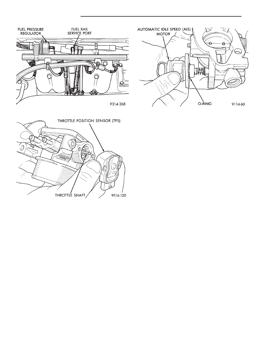
(3) Remove the protective cap from the fuel pres-
sure test port on the fuel rail (Fig. 2).
(4) Place the open end of fuel pressure release
hose, tool number C-4799-1, into an approved gaso-
line container. Connect the other end of hose
C-4799-1 to the fuel pressure test port. Fuel pressure
will bleed off through the hose into the gasoline con-
tainer. Fuel gauge C-4799-A contains hose C-4799-1.
(5) Continue fuel system service.
THROTTLE POSITION SENSOR (TPS)
REMOVAL
(1) Disconnect the negative cable from the battery.
(2) Disconnect harness connector from throttle po-
sition sensor (Fig. 3).
(3) Remove
throttle
position
sensor
mounting
screws.
(4) Lift throttle position sensor off throttle shaft.
Fig. 1 Throttle Body
Ä
FUEL SYSTEMS
14 - 107
INSTALLATION
(1) Install throttle position sensor on throttle shaft.
Install mounting screws. Tighten screws to 2 N
Im (17
in. lbs.) torque.
(2) Attach harness connector to sensor.
(3) Connect negative cable to negative post of the
battery.
IDLE AIR CONTROL MOTOR
REMOVAL
(1) Disconnect negative cable from battery.
(2) Disconnect harness connector from idle air con-
trol motor (Fig. 4).
(3) Remove idle air control motor mounting screws.
(4) Remove the motor from throttle body. Ensure the
O-ring is was removed with the idle air control motor.
INSTALLATION
(1) New idle air control motors have a new O-ring
installed on them. If pintle measures more than 1
inch (25 mm) it must be retracted by using the IDLE
AIR CONTROL MOTOR OPEN/CLOSE mode of the
DRBII scan tool.
(2) Carefully place idle air control motor into
throttle body.
(3) Install mounting screws. Tighten screws to 2
N
Im (17 in. lbs.) torque.
(4) Connect harness connector to motor.
(5) Connect negative cable to battery.
THROTTLE BODY REMOVAL
(1) Disconnect negative cable from battery.
(2) Remove clamp from air hose. Remove hose (Fig.
5).
(3) Remove accelerator cable.
(4) Disconnect idle air control motor and throttle
position sensor (TPS) electrical connectors (Fig. 6).
(5) Disconnect vacuum hoses from throttle body.
(6) Remove throttle body to intake manifold at-
taching nuts (2).
(7) Remove throttle body and gasket.
INSTALLATION
(1) Install throttle body with new gasket.
(2) Install throttle body attaching nuts. Tighten
nuts to 25 N
Im (225 in. lbs.) torque.
(3) Connect vacuum hoses to the throttle body.
(4) Attach harness connectors to the throttle posi-
tion sensor (TPS) and the idle air control motor.
(5) Install throttle and speed control cables (if ap-
plicable).
(6) Install throttle body intake air hose. Tighten
clamp to 4 N
Im (30 in. lbs.) torque.
(7) Connect negative cable to battery.
Fig. 4 Idle Air Control Motor
Fig. 2 Fuel Pressure Test Port
Fig. 3 Throttle Position Sensor
14 - 108
FUEL SYSTEMS
Ä
Нет комментариевНе стесняйтесь поделиться с нами вашим ценным мнением.
Текст