Chrysler Le Baron, Dodge Dynasty, Plymouth Acclaim. Manual — part 73

(8) Remove the upper to lower steering coupler re-
taining nut and pinch bolt (Fig. 6). Remove the upper
steering coupler from the lower steering coupler shaft.
(9) Place the gear shift lever in either the neutral
or park position.
(10) Remove the PRNDL indicator actuation cable
from the steering column actuating arm (Fig. 7).
(11) Release the lock bar on the column insert.
Squeeze the legs of the column insert together and re-
move insert from steering column assembly (Fig. 7).
(12) Secure the insert and actuation cable out of
the way.
(13) Remove tilt lever (if equipped) from steering
column.
(14) Remove the upper and lower lock housing
shrouds (Fig. 1) from the steering column assembly. Re-
move the lower fixed shroud from the steering column
assembly. The shroud fasteners are Torx-head screws.
(15) Remove the wiring harness connector to the
turn
signal/multi-function
switch
using
a
7mm
socket as shown in (Fig. 8).
(16) Remove the electrical connections from the
Key-in Switch & Halo Light, Main Ignition Switch,
Horn connection or Clock Spring (Speed Control
Equipped) (Fig. 9).
(17) Loosen the upper steering column support
bracket nuts (Fig.10) to allow some slack. This will
aid in removal of the upper fixed shroud.
(18) Remove the upper fixed shroud (Fig. 1) from
the steering column assembly. Remove the wiring
harness from the steering column assembly by pry-
ing out the plastic retainer buttons (Fig. 8).
(19) Remove the lower dash panel and support
bracket standoff fasteners (Fig. 1).
(20) Remove the steering column assembly out
through the passenger compartment. Use care to
avoid damaging the paint or interior trim.
Fig. 5 Steering Column Cover Removed
Fig. 6 Steering Column Coupler Remove and Install
Fig. 7 PRNDL Cable Removal
Ä
STEERING
19 - 31
STEERING COLUMN INSTALLATION
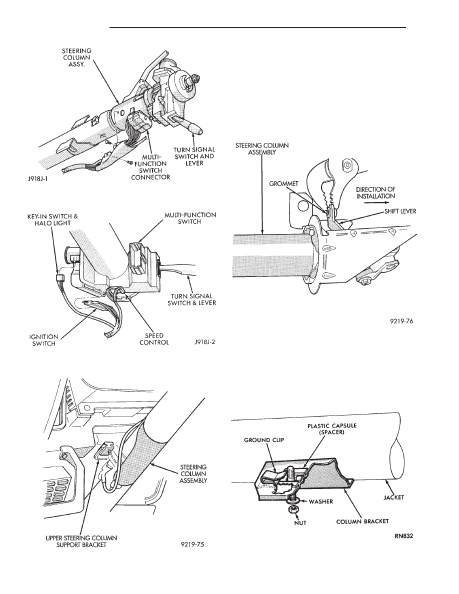
(1) For column shift vehicles, install a new cable
attaching grommet into the steering column
shift lever (Fig. 11). Install grommet from the
cable side of the lever. Use pliers and a back-up
washer to snap the grommet into place (Fig. 11).
Use Mopar
t Multipurpose Lubricant, or equivalent,
to aid installation of the grommet. A replacement
grommet should be used whenever the rod is
disconnected from the lever.
(2) Install the ground clip on the left capsule slot (Fig.
12). The plastic capsules should be pre-assembled in the
bracket slots. Remove the shipping lock pin (Fig. 1)
located on lower column jacket when installing a
new steering column. Insert the column through the
floor pan opening while being careful to avoid damaging
the interior paint and trim.
Fig. 8 Multi-function Switch Wiring Harness
Connector
Fig. 9 Steering Column Wiring
Fig. 10 Steering Column Support Bracket
Fig. 11 Replacement Cable Grommet Installation
Fig. 12 Ground Clip & Spacer Installation
19 - 32
STEERING
Ä
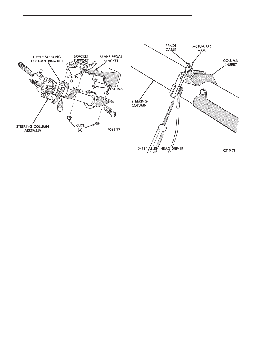
(3) Position the steering column assembly in the
vehicle. Align the steering column assembly mounting
bracket slots on the brake pedal bracket attaching
studs (Fig. 13). Install, but loose assemble the two
upper column bracket, washers and nuts.
(4) Make sure the front wheels are in the straight-
ahead position. Align and assemble the upper steering
coupler to lower steering coupler. Install the upper to
lower steering coupler retaining bolt and nut. Torque
the retaining bolt nut to 28 N
Im (250 in. lbs.). Be sure
to install the upper to lower steering coupler
retaining bolt retention pin (Fig. 6).
(5) Install the buttons which retain the multi func-
tion switch wiring harness to the steering column.
Connect the multi-function switch wiring harness con-
nector to the multi-function switch. Torque the connec-
tor retaining bolt to 2 N
Im (17 in. lbs) using a 7 mm
socket (Fig. 8).
(6) Install the upper fixed shroud onto the steering
column assembly.
(7) Be sure both breakaway capsules are fully seated
in the slots of the steering column upper support
bracket. Torque the 2 upper steering column assembly
to support bracket nuts to 12 N
Im (105 in. lbs.). Torque
the 2 lower steering column assembly to mounting
bracket nuts to 12 N
Im (105 in. lbs.).
(8) Complete the wiring harness connections to the
remaining steering column switches (Fig. 9). Install
the lower fixed shroud onto the steering column.
(9) Route the PRNDL actuator assembly under left
steering column wing and along left side of steering
column. Insert the flange of the PRNDL actuator steering
column insert into the steering column jacket (Fig. 7).
Squeeze the legs of the steering column insert together
and install tabs under steering column jacket. Engage
lock bar to secure the actuator assembly into the steering
column jacket (Fig. 7).
(10) Hook the PRNDL actuator cable eyelet to the
steering column actuator arm (Fig. 7). Move the shift
lever to neutral, check pointer location, should indicate
neutral. If pointer does not indicate neutral adjust actua-
tor with tool (Fig. 14) to center pointer on N (Neutral) and
then check pointer location in other gears.
(11) Install the lock housing shrouds. The shroud
fasteners are Torx-head screws. Install the tilt lever
(if equipped).
(12) Install the lower dash panel cover.
(13) For steering wheel installation with speed con-
trol refer to Group 8 Electrical. For non-speed control,
place the steering wheel on the steering column shaft
with the master splines aligned. Install the steering
wheel to column shaft retaining nut. Tighten retaining
nut to 61 N
Im (45 ft. lbs.) torque. Do not force the
steering wheel onto the column shaft by driving
it on with a heavy object. Pull steering wheel
down onto column shaft using ONLY the steering
wheel retaining nut.
(14) For vehicles equipped with a column shift. Pass
the transmission shift cable through its mounting bracket
on the steering column assembly. Connect the transmis-
sion shift cable to the shift lever on the steering column
assembly. Install the shift cable to mounting bracket
retaining clip (Fig. 2). The grommet must be installed
in the shift lever (Fig. 11) before the cable is in-
serted into the grommet. Use Mopar
t Multipurpose
Lubricant, or an equivalent product, to aid installation of
shift link rod into grommet.
(15) Re-adjust
the
transmission
shift
linkage.
Whenever the steering column is loosened or
removed, the shift linkage MUST be adjusted and
tested. Refer to Group 21 Transmission for the shift
linkage adjustment procedure.
Fig. 13 Steering Column Mounting
Fig. 14 PRNDL Actuator Cable Adjustment
Ä
STEERING
19 - 33
(16) Connect the battery ground (negative) cable.
Test the operation of the lights and horns. If applica-
ble, reset the clock and radio.
STEERING COLUMN COMPONENT SERVICE
The Acustar tilt and standard steering columns
(Fig.1) have been designed to be serviced as an as-
sembly; less wiring, switches, shrouds, steering
wheel, etc. Also most steering column components
can be serviced without removing the steering col-
umn from the vehicle. For additional information on
electrical components refer to Group 8H Electrical.
GEAR SHIFT LEVER
The gear shift lever (if equipped) is a serviceable
component of the Acustar steering column assembly.
REMOVE
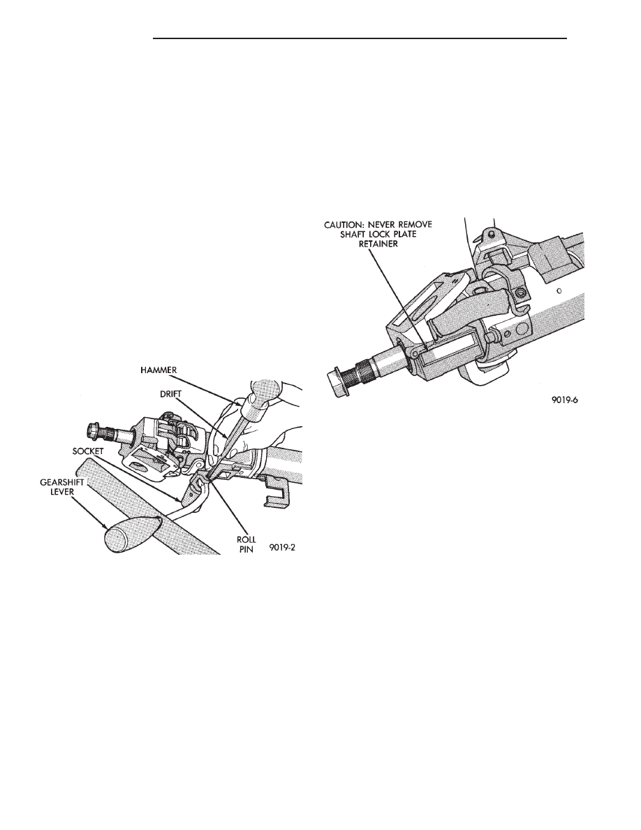
(1) Support
the
steering
column
assembly
as
shown in (Fig. 1) using a suitable size socket.
(2) Using a drift of the appropriate size drive the
roll pin out of the steering column and gear shift le-
ver (Fig. 1). Remove the gear shift lever from the
steering column assembly.
INSTALL
(1) Support
the
steering
column
assembly
as
shown in (Fig. 1) using a suitable size socket.
(2) Install the gear shift lever into the steering col-
umn assembly. Align the roll pin holes in the gear
shift lever and the steering column assembly.
(3) Carefully Install the roll pin into the steering
column assembly and through the shift lever. If the
roll pin binds check the alignment on the holes. Be
sure roll pin is fully installed into the steering col-
umn assembly.
IGNITION SWITCH SERVICE
TEST AND REPAIR
If the ignition switch effort seems to be excessive
due to binding. Follow the procedure outlined below
to determine the cause.
When service procedures are performed on the
Acustar steering column there are certain areas of the
column that can not be tampered with. If a problem re-
lated to these areas of the steering column are detected.
The entire steering column (less the removable compo-
nents) should be replaced see (Fig. 2 and 3).
(1) Remove ignition switch from steering column.
Refer to Group 8H Electrical.
(2) Using a key cylinder, check the turning effort
of the switch.
• If the ignition switch binds look for the following
conditions.
Fig. 1 Gear Shift Lever Removal
Fig. 2 Steering Column Non-Serviceable
Components
19 - 34
STEERING
Ä
Нет комментариевНе стесняйтесь поделиться с нами вашим ценным мнением.
Текст