Chrysler Le Baron, Dodge Dynasty, Plymouth Acclaim. Manual — part 49
3.0L MULTI-PORT FUEL INJECTION—SYSTEM OPERATION
INDEX
page
page
Air Conditioning (A/C) Clutch Relay (AA, AG, AJ
Body)—PCM Output
. . . . . . . . . . . . . . . . . . . . 118
Air Conditioning (A/C) Clutch Relay (AC Body)
—PCM Output
. . . . . . . . . . . . . . . . . . . . . . . . 118
Air Conditioning Switch Sense (AA, AG, AJ
Body)—PCM Input
. . . . . . . . . . . . . . . . . . . . . 115
Air Conditioning Switch Sense (AC Body)—PCM
Input
. . . . . . . . . . . . . . . . . . . . . . . . . . . . . . . . 115
Auto Shutdown (ASD) Relay and Fuel Pump
Relay—PCM Output
. . . . . . . . . . . . . . . . . . . . 119
Battery Voltage—PCM Input
. . . . . . . . . . . . . . . 115
Brake Switch—PCM Input
. . . . . . . . . . . . . . . . . 115
CCD Bus
. . . . . . . . . . . . . . . . . . . . . . . . . . . . . . 113
Data Link Connector—PCM Output
. . . . . . . . . . 120
Distributor Pick-Up—PCM Input
. . . . . . . . . . . . . 115
Duty Cycle Evap Canister Purge Solenoid
—PCM Output
. . . . . . . . . . . . . . . . . . . . . . . . 119
Engine Coolant Temperature Sensor
—PCM Input
. . . . . . . . . . . . . . . . . . . . . . . . . 115
Fuel Injectors—PCM Output
. . . . . . . . . . . . . . . 120
Fuel Pressure Regulator
. . . . . . . . . . . . . . . . . . 124
Fuel Supply Circuit
. . . . . . . . . . . . . . . . . . . . . . 123
General Information
. . . . . . . . . . . . . . . . . . . . . . 113
Generator Field—PCM Output
. . . . . . . . . . . . . . 118
Heated Oxygen Sensor (O
2
Sensor)
—PCM Input
. . . . . . . . . . . . . . . . . . . . . . . . . 116
Idle Air Control Motor—PCM Output
. . . . . . . . . 119
Ignition Coil—PCM Output
. . . . . . . . . . . . . . . . . 121
Malfunction Indicator Lamp (Check Engine
Lamp)—PCM Output
. . . . . . . . . . . . . . . . . . . 120
Manifold Absolute Pressure (MAP) Sensor
—PCM Input
. . . . . . . . . . . . . . . . . . . . . . . . . 116
Modes of Operation
. . . . . . . . . . . . . . . . . . . . . . 121
Park/Neutral Switch—PCM Input
. . . . . . . . . . . . 117
Part Throttle Unlock Solenoid—PCM Output
. . . 121
Powertrain Control Module
. . . . . . . . . . . . . . . . . 113
Radiator Fan Relay—PCM Output
. . . . . . . . . . . 121
Speed Control Solenoids—PCM Output
. . . . . . . 121
Speed Control—PCM Input
. . . . . . . . . . . . . . . . 117
System Diagnosis
. . . . . . . . . . . . . . . . . . . . . . . 113
Tachometer—PCM Output
. . . . . . . . . . . . . . . . . 121
Throttle Body
. . . . . . . . . . . . . . . . . . . . . . . . . . . 123
Throttle Position Sensor (TPS)—PCM Input
. . . . 117
Transaxle Control Module—PCM Output
. . . . . . 120
Vehicle Speed and Distance Input—PCM Input
. 118
Vehicle Speed Sensor—PCM Input
. . . . . . . . . . 118
GENERAL INFORMATION
The 3.0L engine uses a sequential Multi-Port Elec-
tronic Fuel Injection system (Fig. 1). The MPI system
is computer regulated and provides precise air/fuel
ratios for all driving conditions.
The MPI system is operated by the powertrain con-
trol module (PCM).
The PCM regulates ignition timing, air-fuel ratio,
emission control devices, cooling fan, charging sys-
tem, idle speed and speed control. Various sensors
provide the inputs necessary for the PCM to correctly
operate these systems. In addition to the sensors,
various switches also provide inputs to the PCM.
All inputs to the PCM are converted into signals.
The PCM can adapt its programming to meet chang-
ing operating conditions.
Fuel is injected into the intake port above the in-
take valve in precise metered amounts through elec-
trically
operated
injectors.
The
PCM
fires
the
injectors in a specific sequence. The PCM maintains
an air fuel ratio of 14.7 parts air to 1 part fuel by
constantly adjusting injector pulse width. Injector
pulse width is the length of time the injector is ener-
gized.
The PCM adjusts injector pulse width by opening
and closing the ground path to the injector. Engine
RPM (speed) and manifold absolute pressure (air
density) are the primary inputs that determine injec-
tor pulse width.
SYSTEM DIAGNOSIS
The powertrain control module (PCM) tests many
of its own input and output circuits. If a fault is
found in a major system, the information is stored in
memory. Technicians can display fault information
through the malfunction indicator lamp (instrument
panel Check Engine lamp) or by connecting the
DRBII scan tool. For diagnostic trouble code informa-
tion, refer to the 3.0 Multi-Port Fuel Injection—On-
Board Diagnostics section of this group.
CCD BUS
Various modules exchange information through a
communications port called the CCD Bus. The pow-
ertrain control module (PCM) transmits the malfunc-
tion indicator (instrument panel check engine lamp)
On/Off signal, engine RPM and vehicle load data on
the CCD Bus.
POWERTRAIN CONTROL MODULE
The powertrain control module (PCM) is a digital
computer containing a microprocessor (Fig. 2). The
PCM receives input signals from various switches
and sensors that are referred to as PCM Inputs.
Based on these inputs, the PCM adjusts various en-
gine and vehicle operations through devices referred
to as PCM Outputs.
PCM Inputs:
• Air Conditioning Controls
• Battery Voltage
• Brake Switch
Ä
FUEL SYSTEMS
14 - 113

• Engine Coolant Temperature Sensor
• Distributor Pick-up
• Manifold Absolute Pressure (MAP) Sensor
• Oxygen Sensor
• SCI Receive
• Speed Control System Controls
• Throttle Position Sensor
• Park/Neutral Switch (automatic transaxle)
• Vehicle Speed Sensor
PCM Outputs:
• Air Conditioning Clutch Relay
• Generator Field
• Idle Air Control Motor
• Auto Shutdown (ASD) and Fuel Pump Relays
• Canister Purge Solenoid
• Malfunction Indicator Lamp (Check Engine Lamp)
• Data Link Connector
• Electric EGR Transducer (EET)
• Fuel Injectors
• Ignition Coil
• Torque Converter Clutch Solenoid
• Radiator Fan Relay
• Speed Control Solenoids
• Tachometer Output
Based on inputs it receives, the PCM adjusts fuel
injector pulse width, idle speed, ignition spark ad-
vance, ignition coil dwell and canister purge opera-
tion.
The
PCM
regulates
the
cooling
fan,
air
conditioning and speed control systems. The PCM
changes generator charge rate by adjusting the gen-
erator field.
The PCM adjusts injector pulse width (air-fuel ra-
tio) based on the following inputs.
• battery voltage
• engine coolant temperature
• exhaust gas content
• engine speed (distributor pick-up)
• manifold absolute pressure
• throttle position
Fig. 1 Multi-Port Fuel Injection Components
Fig. 2 PCM
14 - 114
FUEL SYSTEMS
Ä
The PCM adjusts ignition timing based on the fol-
lowing inputs.
• engine coolant temperature
• engine speed (distributor pick-up)
• manifold absolute pressure
• throttle position
The Automatic Shut Down (ASD) and Fuel Pump
relays are mounted externally, but turned on and off
by the PCM through the same circuit.
The distributor pick-up signal is sent to the PCM.
If the PCM does not receive a distributor signal
within approximately one second of engine cranking,
the ASD relay and fuel pump relay are deactivated.
When these relays are deactivated, power is shut off
to the fuel injector, ignition coil, oxygen sensor heat-
ing element and fuel pump.
The
PCM
contains
a
voltage
converter
that
changes battery voltage to a regulated 8.0 volts. The
8.0 volts power the distributor pick-up and vehicle
speed sensor. The PCM also provides a 5.0 volts sup-
ply for the coolant temperature sensor, manifold ab-
solute pressure sensor and throttle position sensor.
AIR CONDITIONING SWITCH SENSE (AA, AG, AJ
BODY)—PCM INPUT
When the air conditioning or defrost switch is in
the ON position and the low pressure and high pres-
sure switches are closed, the PCM receives an input
for air conditioning. After receiving this input, the
PCM activates the A/C compressor clutch by ground-
ing the A/C clutch relay. The PCM also adjusts idle
speed to a scheduled RPM to compensate for in-
creased engine load.
AIR CONDITIONING SWITCH SENSE (AC
BODY)—PCM INPUT
When the air conditioning or defrost switch is in
the ON position and the low pressure, high pressure
and ambient temperature switches are closed, the
PCM receives an input for air conditioning. After re-
ceiving this input, the PCM activates the A/C com-
pressor clutch by grounding the A/C clutch relay.
The PCM also adjusts idle speed to a scheduled RPM
to compensate for increased engine load.
BATTERY VOLTAGE—PCM INPUT
The PCM monitors the battery voltage input to de-
termine fuel injector pulse width and generator field
control. If battery voltage is low, the PCM will in-
crease injector pulse width.
BRAKE SWITCH—PCM INPUT
When the brake switch is activated, the PCM re-
ceives an input indicating that the brakes are being
applied. After receiving this input the PCM main-
tains idle speed to a scheduled RPM through the idle
air control motor. The brake switch is mounted on
the brake pedal support bracket.
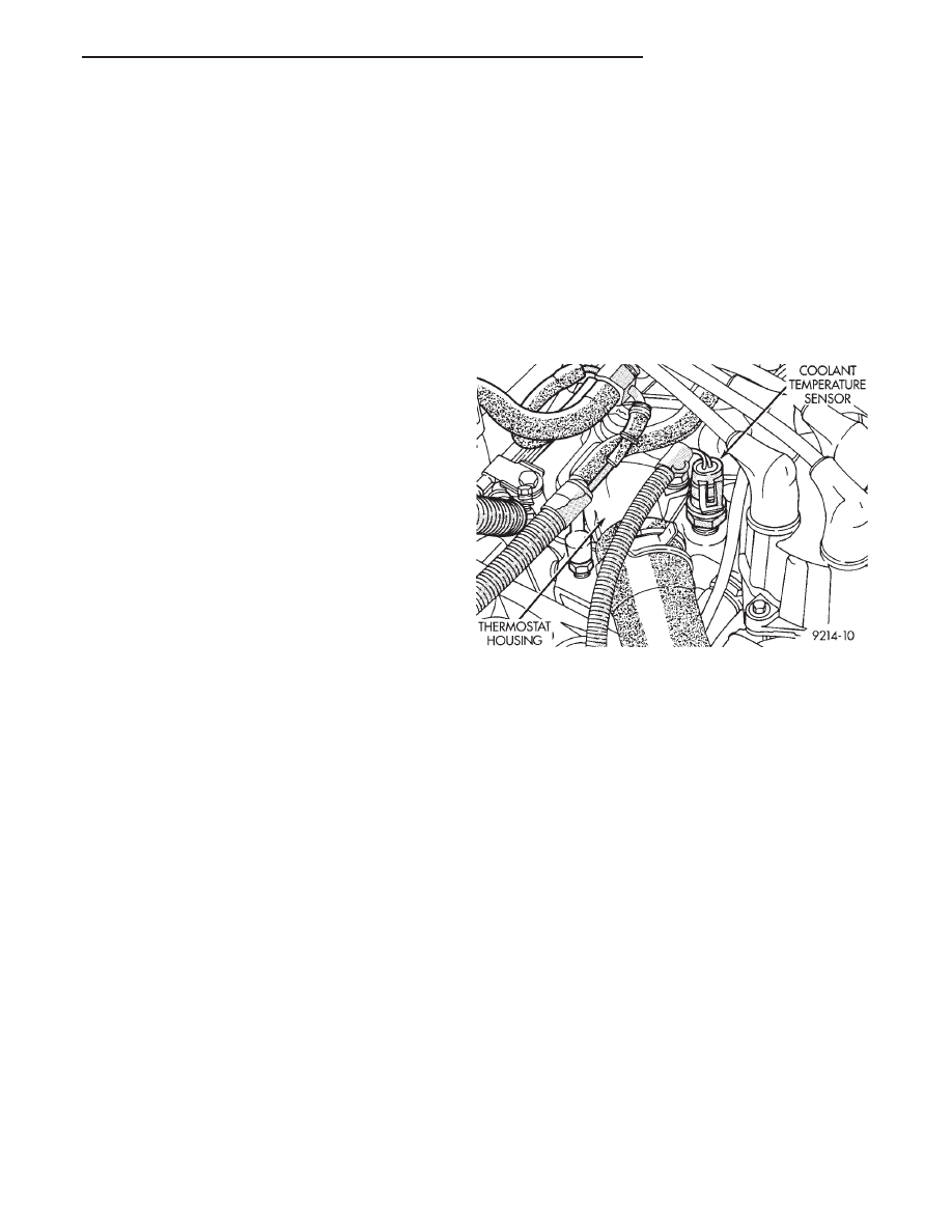
ENGINE COOLANT TEMPERATURE SENSOR—PCM
INPUT
The coolant temperature sensor is a variable resis-
tor with a range of -40° to 265°. The sensor is in-
stalled next to the thermostat housing.
The PCM supplies 5.0 volts to the coolant temper-
ature sensor. The sensor provides an input voltage to
the PCM (Fig. 3). As coolant temperature varies, the
sensors resistance changes, resulting in a different
input voltage to the PCM.
The PCM demands slightly richer air-fuel mixtures
and higher idle speeds until the engine reaches nor-
mal operating temperature.
This sensor is also used for cooling fan control.
DISTRIBUTOR PICK-UP—PCM INPUT
The distributor pick-up provides two inputs to the
PCM. From one input the PCM determines RPM (en-
gine speed). From the other input it derives crank-
shaft
position.
The
PCM
regulates
injector
synchronization and adjusts ignition timing and en-
gine speed based on these inputs.
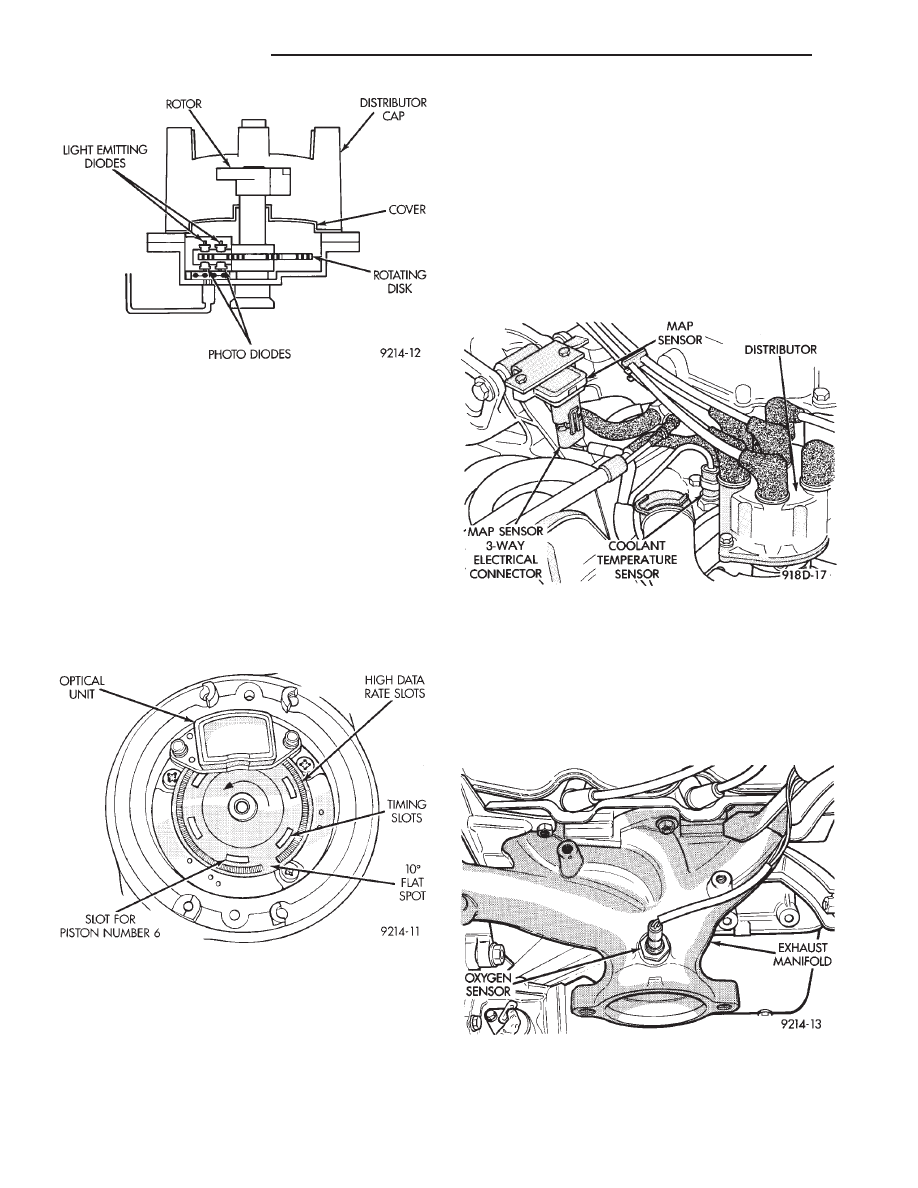
The distributor pick-up contains two signal gener-
ators. The pick-up unit consists of 2 light emitting
diodes (LED), 2 photo diodes, and a separate timing
disk. The timing disk contains two sets of slots. Each
set of slots rotates between a light emitting diode
and a photo diode (Fig. 4). The inner set contains 6
large slots, one for each cylinder. The outer set con-
tains several smaller slots.
The outer set of slots on the rotating disk repre-
sents 2 degrees of crankshaft rotation. Up to 1200
engine RPM, the PCM uses the input from the outer
set of slots to increase ignition timing accuracy.
The outer set of slots contains a 10 degree flat spot
(Fig. 5). The flat spot tells the PCM that the next
piston at TDC will be number 6. The position of each
piston is referenced by one of the six inner slots (Fig.
5).
As each slot on the timing disk passes between the
diodes, the beam from the light emitting diode is in-
Fig. 3 Coolant Temperature Sensor
Ä
FUEL SYSTEMS
14 - 115
terrupted. This creates an alternating voltage in
each photo diode which is converted into on-off
pulses. The pulses are the input to the PCM.
During
cranking,
the
PCM
cannot
determine
crankshaft position until the 10 degree flat spot on
the outer set of slots passes through the optical unit.
Once the flat spot is detected, the PCM knows piston
number 6 will be the next piston at TDC.
Since the disk rotates at half crankshaft speed, it
may take 2 engine revolutions during cranking for
the PCM to determine the position of piston number
6. For this reason the PCM will energize all six in-
jectors at the same time until it senses the position
of piston number 6.
MANIFOLD ABSOLUTE PRESSURE (MAP)
SENSOR—PCM INPUT
The PCM supplies 5 volts to the MAP sensor. The
Map sensor converts intake manifold pressure into
voltage. The PCM monitors the MAP sensor output
voltage. As vacuum increases, MAP sensor voltage
decreases proportionately. Also, as vacuum decreases,
MAP sensor voltage increases proportionately.
During cranking, before the engine starts running,
the PCM determines atmospheric air pressure from
the MAP sensor voltage. While the engine operates,
the PCM determines intake manifold pressure from
the MAP sensor voltage.
Based on MAP sensor voltage and inputs from
other sensors, the PCM adjusts spark advance and
the air/fuel mixture.
The MAP sensor (Fig. 6) mounts on a bracket at-
tached to the generator bracket. The sensor is con-
nected to the throttle body with a vacuum hose and
to the PCM electrically.
HEATED OXYGEN SENSOR (O
2
SENSOR)—PCM
INPUT
The O
2
sensor is located in the exhaust manifold
and provides an input voltage to the PCM. The input
tells the PCM the oxygen content of the exhaust gas
(Fig. 7). The PCM uses this information to fine tune
the air-fuel ratio by adjusting injector pulse width.
The O
2
sensor produces voltages from 0 to 1 volt,
depending upon the oxygen content of the exhaust
gas. When a large amount of oxygen is present
Fig. 4 Distributor Pick-up
Fig. 5 Inner and Outer Slots of Rotating Disk
Fig. 6 Map Sensor
Fig. 7 Heated Oxygen Sensor—3.0L Engine
14 - 116
FUEL SYSTEMS
Ä
Нет комментариевНе стесняйтесь поделиться с нами вашим ценным мнением.
Текст