SsangYong Korando II (1996-2006 year). Manual — part 172
OM600 ENGINE MECHANICAL 1B3 -- 137
DAEWOO MY_2000
CAMSHAFT TIMING TEST
Preceding Work : Removal of glow plug
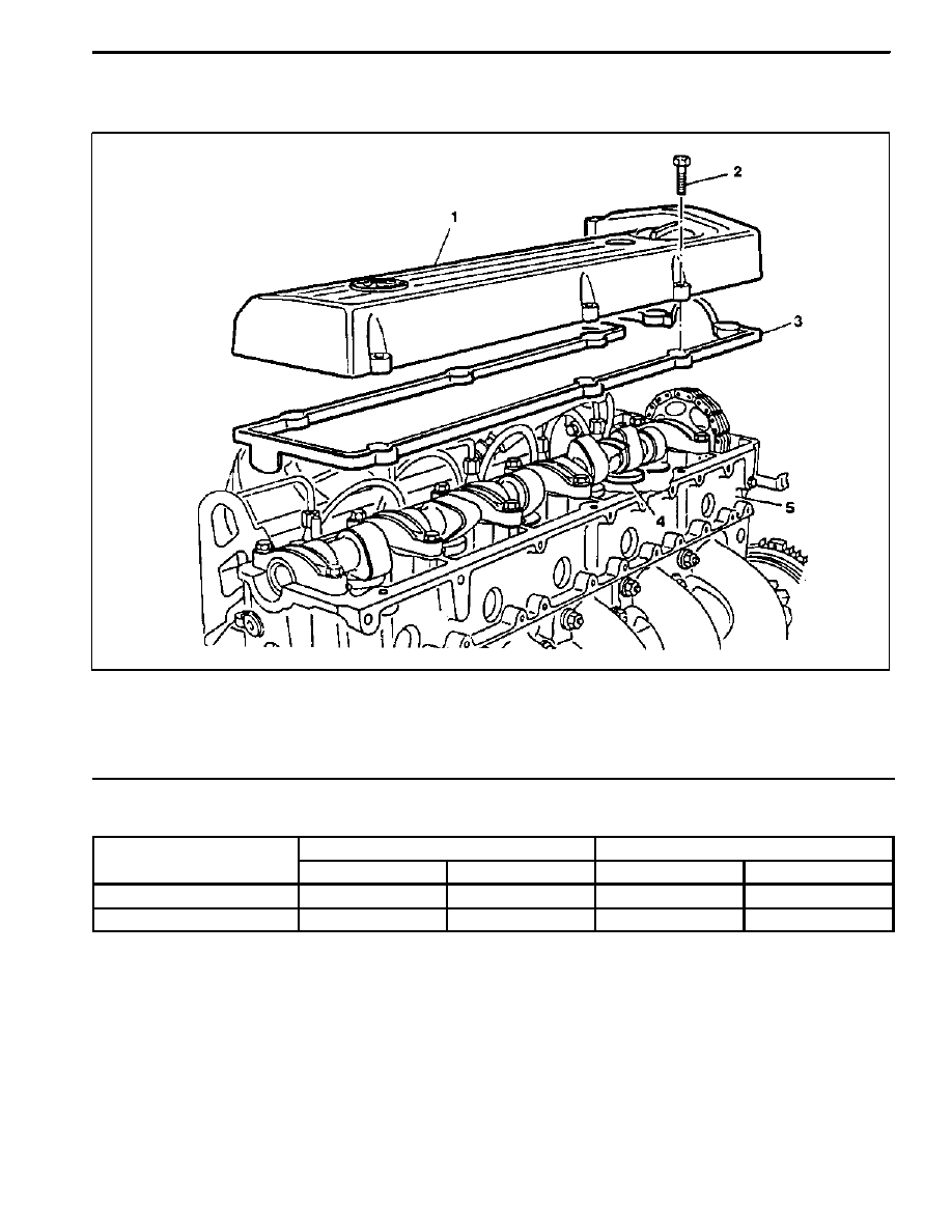
1 Cylinder Head Cover
2 Bolt
10N∙m (89 lb-in)
. . . . . . . . . . . . . . . . . . . . .
3 Gasket
Replace
. . . . . . . . . . . . . . . . . . . . . . . . . .
4 Valve Tappet
5 Cylinder Head
Timing
C diti
f
h ft
Intake valve
Exhaust valve
Condition of camshaft
Open
Close
Open
Close
New
ATDC 11.33_
ABDC 17_
BBDC 28_
BTDC 15.25_
After approx. 20,000km
ATDC 12_
ABDC 18_
BBDC 27_
BTDC 14_
* At 2mm of valve lifting stroke.

1B3 -- 138 OM600 ENGINE MECHANICAL
DAEWOO MY_2000
Tools Required
001 589 53 21 00 Dial Gauge
363 589 02 21 00 Dial Gauge Holder
366 589 00 21 05 Extension
Measurement Procedure
1. Remove the cylinder head cover.
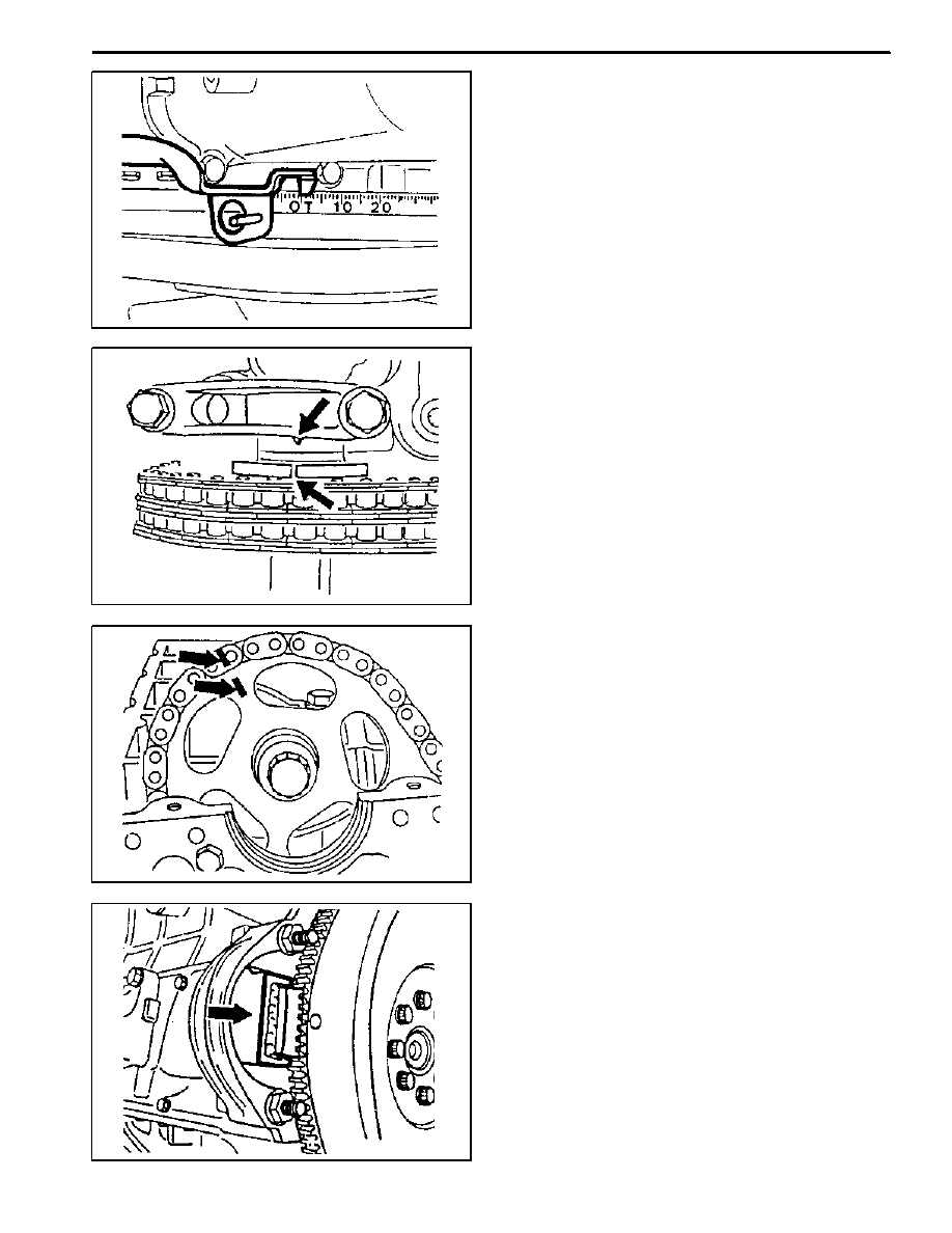
2. Rotate the engine in the direction of engine rotation
until the intake valve of NO.1 cylinder is completely
closed. The cam lobe faces up (arrow).
Notice
Do not rotate the engine at the bolt of the crankshaft
sprocket. Do not rotate the engine in the opposite di-
rection of engine rotation. If do, this will cause seri-
ous measuring errors.
3. Install the dial gauge holder and dial gauge (7) with
the extension (8) to the cylinder head and position
the tracer pin (9) onto the valve tappet (intake valve
of cylinder NO.1) with a preload of min. 3mm.
Notice
The tracer pin should be positioned exactly vertical.
Dial gauge Holder 363 589 02 21 00
Dial Gauge 001 589 53 21 00
Extension 366 589 00 21 05
4. Set the dial gauge to ’0’.
5. Rotate the engine further in direction of rotation until
the dial gauge has moved back by 2mm (valve lift) to
1mm.
6. Check the timing.
New
ATDC 11.33_
After approx. 20,000km
ATDC 12_
Notice
If timing is out standard, the camshaft should be
checked for wear and the timing chain for stretch. If
a difference of more than 4_ exists, the timing chain
should be replaced.
7. Replace the gasket and install the cylinder head
cover.
Tightening Torque
10 N∙m (89 lb-in)
OM600 ENGINE MECHANICAL 1B3 -- 139
DAEWOO MY_2000
CAMSHAFT
Preceding Work : Removal of cylinder head cover
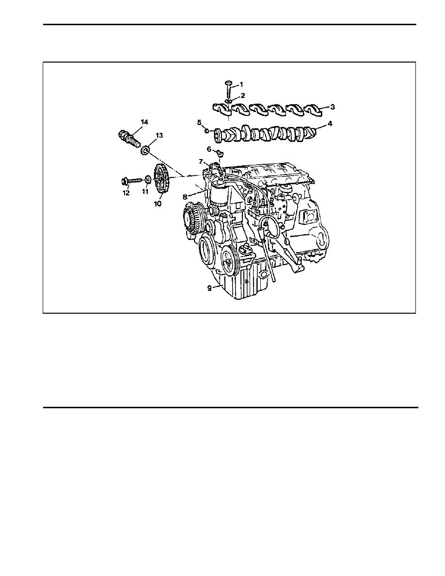
1 Bolt
25N∙m (18 lb-ft)
. . . . . . . . . . . . . . . . . . . . . .
2 Washer
3 Camshaft Bearing Cap
4 Camshaft
5 Dowel Pin
6 Locking Washer
7 Timing Chain
8 Cylinder Head
9 Oil Pan
10 Camshaft Sprocket
11 Washer
12 12--Sided Bolt (M11)
Check, 25N∙m (18 lb-ft)+90_
. . . . . . . . . . . . . . .
13 Gasket
Replace
. . . . . . . . . . . . . . . . . . . . . . . . . .
14 Chain Tensioner
80N∙m (59 lb-ft)
. . . . . . . . . . . .
1B3 -- 140 OM600 ENGINE MECHANICAL
DAEWOO MY_2000
Tools Required
602 589 00 40 00 Engine Lock
Removal Procedure
1. Rotate the crankshaft and position the piston of no.1
cylinder at TDC.
Notice
Do not rotate the crankshaft in the opposite direction
of engine rotation.
In this position, the markings of the camshaft/cam-
shaft bearing cap (arrow) must be aligned.
2. Place alignment marks on the camshaft sprocket
and timing chain.
3. Remove the starter motor and install the engine
lock.
Engine Lock 602 589 00 40 00
Нет комментариевНе стесняйтесь поделиться с нами вашим ценным мнением.
Текст