SsangYong Korando II (1996-2006 year). Manual — part 96
M161 ENGINE MECHANICAL 1B2 -- 89
DAEWOO MY_2000
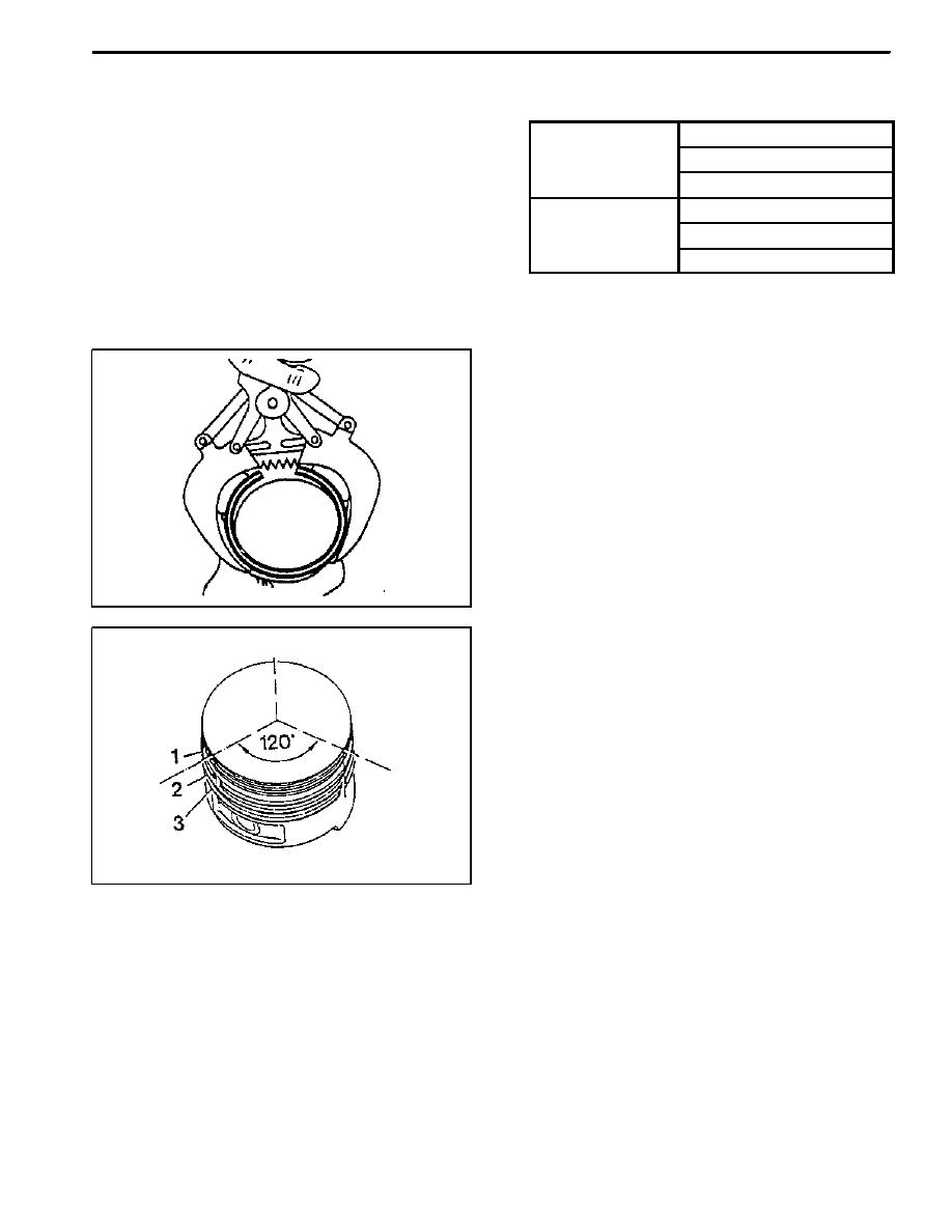
Replacement Procedure
1. Measure the piston ring’s gap.
E d G
f Th
Groove 1 0.20 -- 0.40 mm
End Gap of The
Piston Ring
Groove 2 0.20 -- 0.40 mm
Piston Ring
Groove 3 0.20 -- 0.45 mm
Gap Between
Groove 1 0.028 -- 0.060 mm
Gap Between
The Piston and
Th Pi t
Ri
Groove 2 0.010 -- 0.045 mm
The Piston Ring
Groove 3 0.010 -- 0.045 mm
Notice: If out of specification, replace the piston ring.
2. Remove the piston ring with a pliers.
3. For installation, position the piston ring to be the
‘TOP’ mark on the piston ring upward and arrange the
piston ring ends to be 120° apart.
4. Adjust the hook spring joint in the oil ring 180° away
from the ring end.
1B2 -- 90 M161 ENGINE MECHANICAL
DAEWOO MY_2000
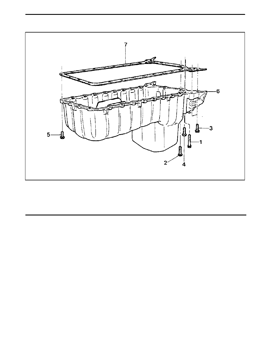
OIL PAN
1 Bolt
2 Bolt
3 Bolt
4 Bolt
5 Bolt
6 Oil Pan
7 Gasket
Removal & Installation Procedure
1. Remove the drain plug and drain the oil completely.
2. Unscrew the bolts and remove the oil pan and gasket.
Notice: Arrange the bolts according to each size.
3. Clean the inside of oil pan and sealing surface, then
apply the sealant.
4. Replace the gasket with new one.
5. Install the oil pan with gasket, and tighten each bolt in
specified torque.
6. Check for oil leaks while running the engine.
M161 ENGINE MECHANICAL 1B2 -- 91
DAEWOO MY_2000
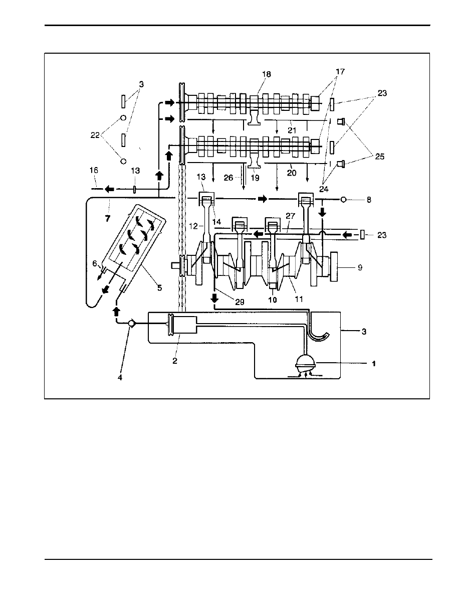
Oil Circulation
1 Oil Strainer
2 Oil Pump
3 Oil Pan
4 Oil Non--Return Valve
5 Oil Filter
6 Oil Filter Bypass Valve
7 Main Oil Gallery
8 Closing Ball (φ 15mm)
9 Crankshaft
10 Connecting Rod Bearing
11 Crankshaft Bearing
12 Connecting Rod
13 Piston
14 Oil Spray (Piston Crown Area)
15 Non--Return Valve (Crankcase)
16 Oil Supply (To Chain Tensioner)
17 Camshaft
18 Cam Bearing
19 Valve
20 Oil Gallery (Supply Oil to Intake Tappet)
21 Oil Gallery (Supply Oil to Exhaust Tappet)
22 Ball (φ 8mm)
23 Camshaft Plug
24 Seal
25 Screw Plug
26 Oil Return Gallery
(Cylinder Head and Crankcase)
27 Oil Return Gallery (Crankcase)
28 End Cover (φ 20mm)
29 Oil Return Pipe

M161 ENGINE MECHANICAL 1B2 -- 97
DAEWOO MY_2000
OIL PRESSURE RELIEF VALVE
Preceding Work: Removal of oil pan
1 Screw Plug
50 NSm (37 lb-ft)
. . . . . . . . . . . . . . . .
2 Compression Spring
3 Guide Pin
4 Piston
Removal & Installation Procedure
1. Remove the screw plug (1).
Installation Notice
Tightening Torque
50 NSm (37 lb-ft)
2. Remove the spring (2), guide pin (3) and the piston
(4).
3. Installation should follow the removal procedure in
the reverse order.
Notice: Don’t use the seal for the screw plug.
Нет комментариевНе стесняйтесь поделиться с нами вашим ценным мнением.
Текст