SsangYong Korando II (1996-2006 year). Manual — part 94
M161 ENGINE MECHANICAL 1B2 -- 81
DAEWOO MY_2000
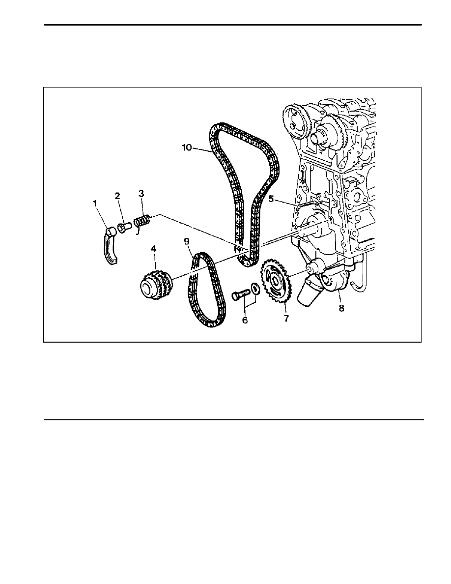
CRANKSHAFT SPROCKET
Preceding Work: Removal of oil pan
Removal of tensioning rail
Removal of crank case guide rail
1 Oil Pump Chain Tensioner
2 Oil Pump Chain Bushing
3 Oil Pump Chain Spring
4 Crankshaft Sprocket
5 Key
6 Bolt (M8 x 20, 1 piece) / Washer
29--35 NSm (21--26 lb-ft)
. . . . . . . . . . . . . . . . . . .
7 Oil Pump Sprocket
8 Oil Pump
9 Oil Pump Roller Chain
10 Timing Chain
1B2 -- 82 M161 ENGINE MECHANICAL
DAEWOO MY_2000
Tools Required
615 589 01 33 00 Crankshaft Sprocket Puller
Removal & Installation Procedure
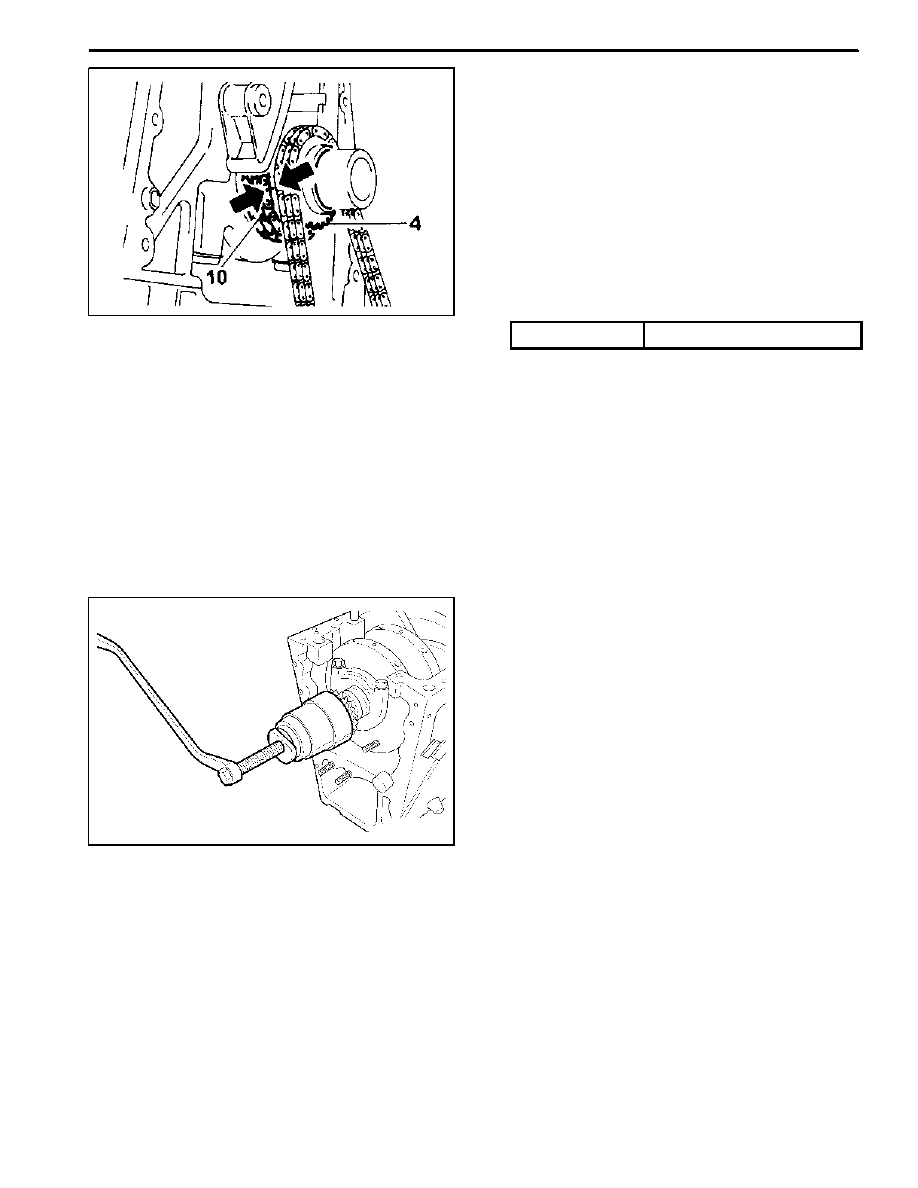
1. Put the assembly mark at the crankshaft sprocket (4)
and the timing chain (10) with the paint (arrow).
Installation Notice
Align the assembly marks on crankshaft sprocket and
timing chain. Also, align the assembly marks on cam-
shaft sprocket and timing chain when installing.
2. Unscrew the bolt (6) and remove the oil pump sprock-
et (7) from the oil pump.
Installation Notice
Tightening Torque
29 -- 35 NSm (21 -- 26 lb-ft)
3. Remove the oil pump roller chain (9).
4. Remove the oil pump chain tensioner (1), oil pump
chain bushing (3), and the oil pump chain spring (2).
5. Remove the crankshaft sprocket (4) using crankshaft
sprocket puller 615 589 01 33 00.
Notice:
D
Make sure not to lose the crankshaft pulley key (5)
when removing.
D
Install the crankshaft sprocket (4) after warming it up.
6. Installation should follow the removal procedure in
the reverse order.
M161 ENGINE MECHANICAL 1B2 -- 83
DAEWOO MY_2000
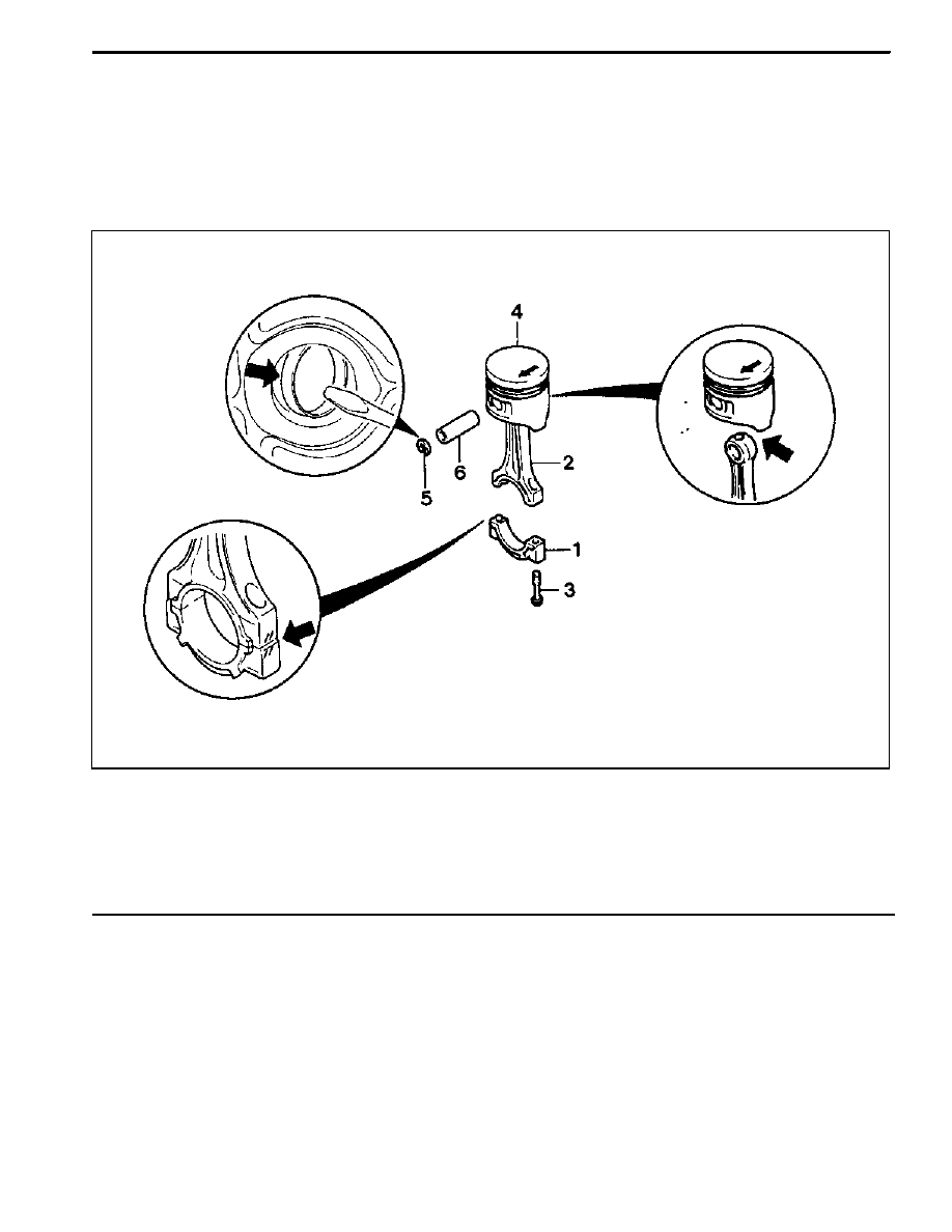
PISTON
Preceding Work: Removal of engine
Removal of cylinder head
Removal of oil pan
Removal of oil pump
Removal of baffle plate
1 Connecting Rod Bearing Cap
2 Connecting Rod
3 Connecting Rod Bolt (M9 x 52, 8 pieces)
1st step 40 NSm (30 lb-ft)
. . . . . . . . . . . . . . . . . .
2nd step 90°
4 Piston
5 Snap Ring
6 Piston Pin
1B2 -- 84 M161 ENGINE MECHANICAL
DAEWOO MY_2000
Removal Procedure
1. Unscrew the connecting rod bolt (3) and remove the
cap.
2. Remove the connecting rod and the piston upward.
Notice: Make sure that the bearing cap and shell are not
changed each other.
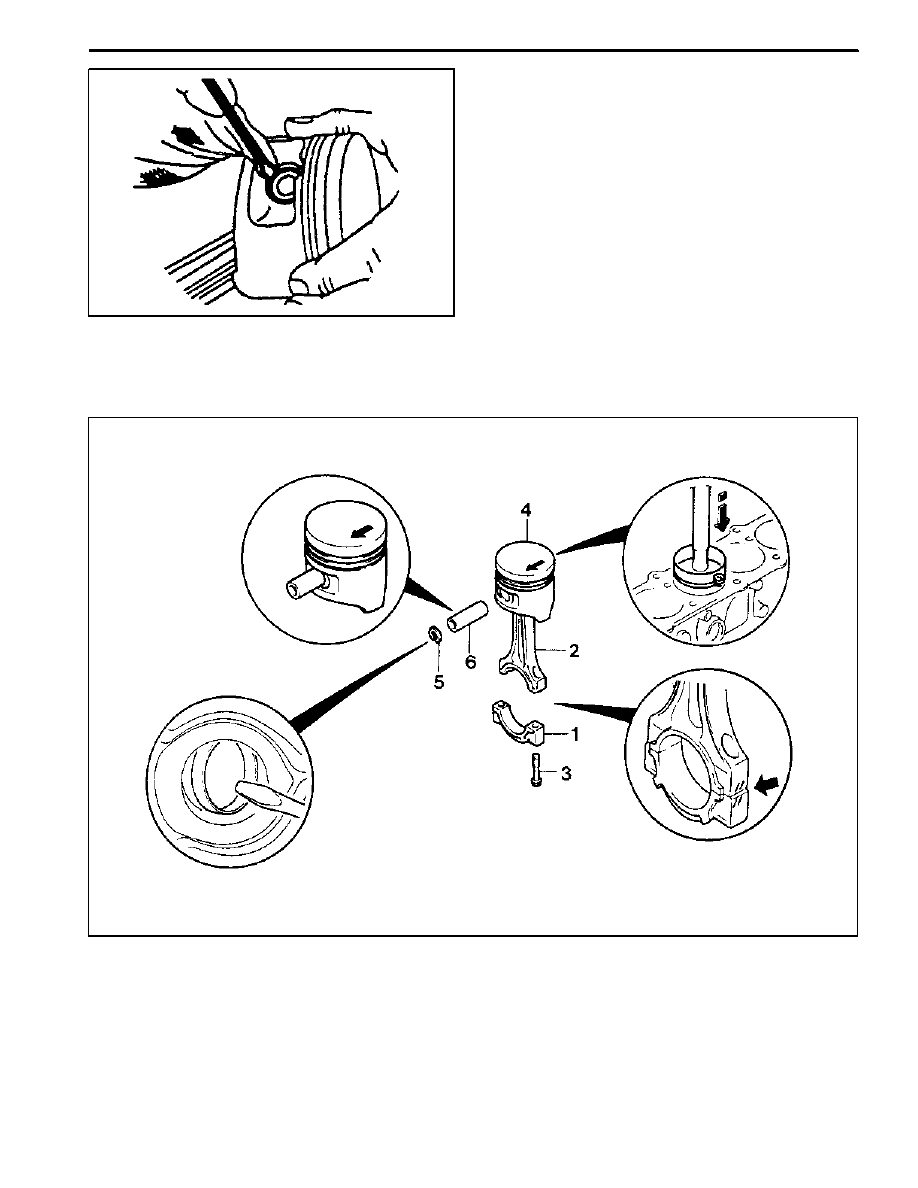
3. Remove the snap ring (5) and pull out the piston pin
(6).
Notice: Remove the snap ring using a clean cloth as
shown in the right picture so that the piston, piston ring,
and the snap ring don’t get damaged.
Installation Procedure
Нет комментариевНе стесняйтесь поделиться с нами вашим ценным мнением.
Текст