SsangYong Korando II (1996-2006 year). Manual — part 90
M161 ENGINE MECHANICAL 1B2 -- 65
DAEWOO MY_2000
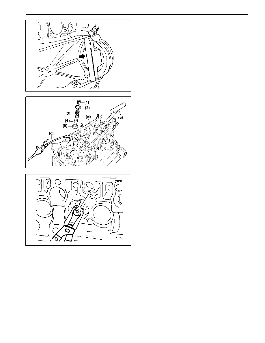
5. Install the engine lock 602 589 00 40 00 to the ring
gear to prevent the crankshaft from rotating.
6. Blow up with compressed air.
7. Install the supporting bar 111 589 01 59 00 (d) and
the lever pusher 111 589 18 61 00 (a).
8. Mount the thrust piece 111 589 25 63 00 (b) vertical-
ly to the valve spring retainer (2).
9. Press the valve spring (3) by using the lever pusher
111 589 18 61 00 (a).
10. Remove the valve cotter (1) using the pincette.
11. Remove the upper retainer (2) and the valve spring
(3).
12. Remove the valve stem seal (4) and replace if nec-
essary.
Notice: Check the valve stem seal for damage and re-
place if necessary.
13. Remove the lower retainer (5).
Notice: Check the retainer for damages and replace
with a new one if necessary.
14. Installation should follow the removal procedure in
the reverse order.
1B2 -- 66 M161 ENGINE MECHANICAL
DAEWOO MY_2000
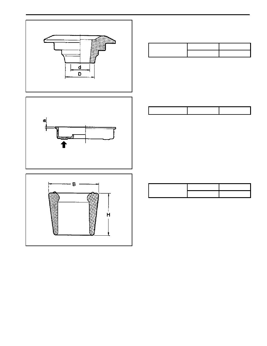
Test (Upper and Lower Valve Tappet and
Valve Cotter)
D
Upper Valve Spring Retainer
Size (mm)
(d)
8.5
Size (mm)
(D)
12.3
D
Lower Valve Spring Retainer
Thickness (mm)
(a)
0.8 -- 1.0
D
Valve Cotter
Size (mm)
(B)
9.0
Size (mm)
(H)
9.2 -- 9.8
M161 ENGINE MECHANICAL 1B2 -- 67
DAEWOO MY_2000
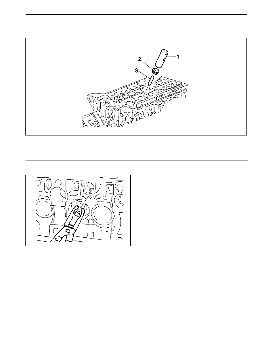
VALVE STEM SEAL
Preceding Work: Removal of valve spring
1 Drift 119 589 00 43 00
2 Valve Stem Seal
3 Protective Sleeve
Tools Required
119 589 00 43 00 Drift
Replacement Procedure
1. Remove the valve stem seal (2) using the pliers.
Notice: Check the valve stem seal for damage and re-
place if necessary.
2. Coat the valve stem seal with oil and assemble it with
the protective sleeve.
3. Insert the valve stem seal by pressing it with the drift
119 589 00 43 00.
1B2 -- 68 M161 ENGINE MECHANICAL
DAEWOO MY_2000
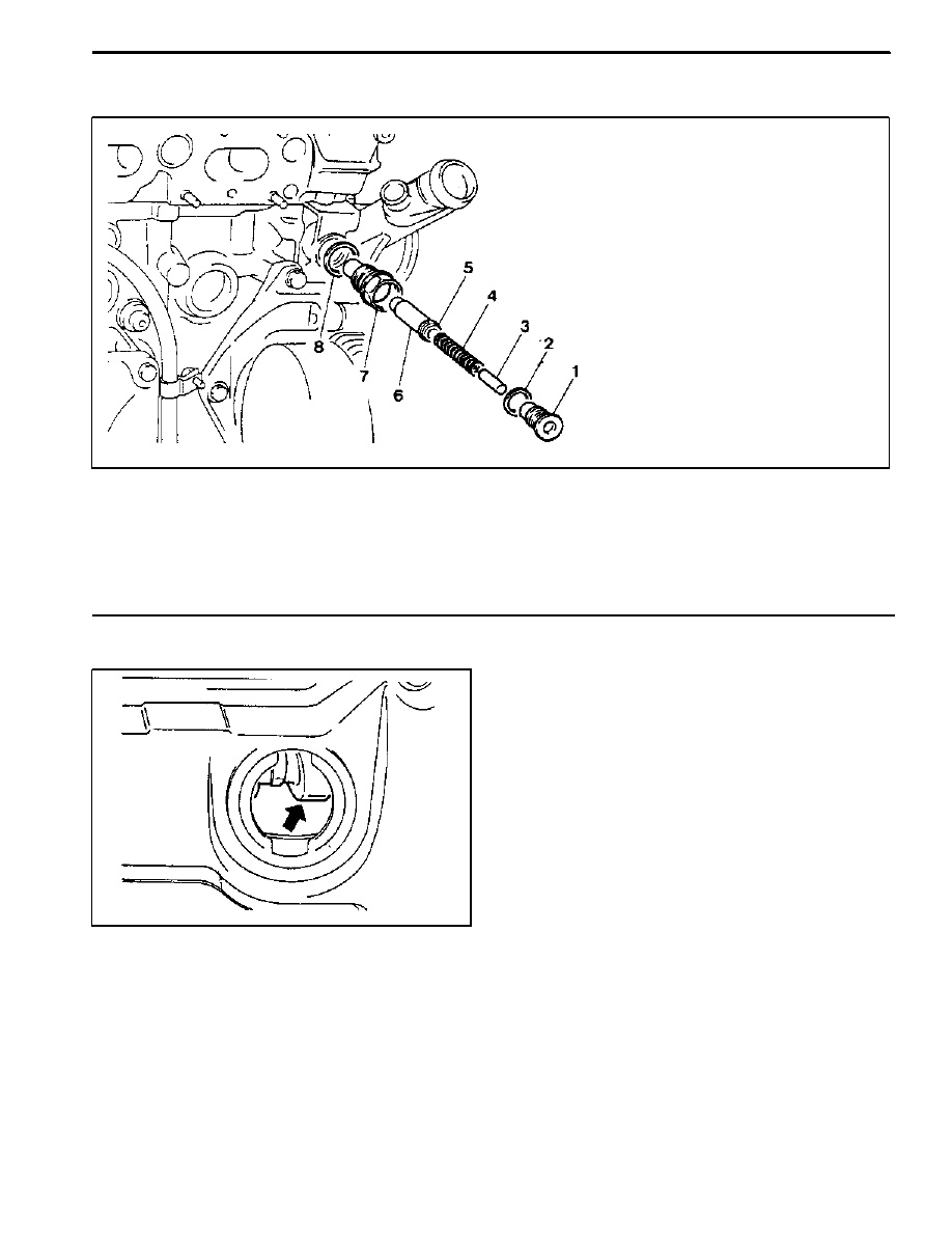
CHAIN TENSIONER
1 Screw Plug
40 NSm (30 lb-ft)
. . . . . . . . . . . . . . . .
2 Seal
3 Filler Pin
4 Compression Spring
5 Snap Ring
6 Thrust Pin
7 Chain Tensioner Housing
72--88 NSm (53--65 lb-ft)
. . . . . . . . . . . . . . . . . . . .
8 Seal
Removal Procedure
1. Position the number 1 cylinder to ATDC 20°.
Notice: Remove the oil filler cap at adjustment position,
and check whether the intake camshaft cam’s lobe (ar-
row) stays in the upper side.
2. Cover the generator with a clean cloth.
3. Release the tension by unscrewing the screw plug
once.
Notice: In case that the tension is reduced by unscrew-
ing the screw plug, reinstall after completely removing
the chain tensioner. If the chain tensioner is tightened
again without completely reducing its tension, then the
snap ring doesn’t return to the original position and the
tension gets exceeded.
Нет комментариевНе стесняйтесь поделиться с нами вашим ценным мнением.
Текст