SsangYong Korando II (1996-2006 year). Manual — part 350
SSANGYONG MY2002
5D1-76 TRANSFER CASE
KAA5D440
KAA5D430
KAA5D420
KAA5D410
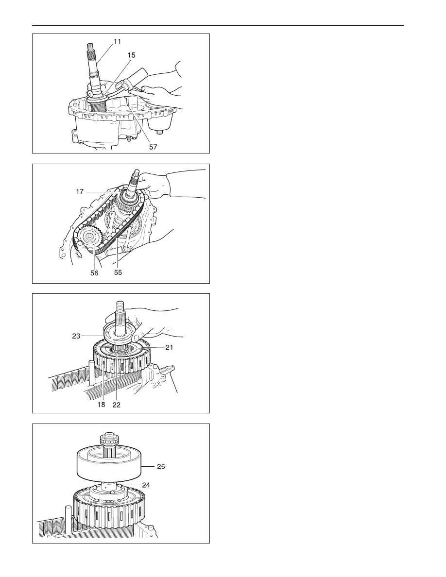
11. Install the output shaft and oil pump in the input
shaft
Notice:
•
If a new pump is used, align the flat of the
output shaft and the flat of the pump. Slide the
pump onto the rear output shaft.
•
Do not remove the plastic insert from the bore
of the new pump. Discard it after it slides out
during pump installation to the rear output shaft.
•
While turning the output shaft, prime the pump
through the oil filter pickup tube or housing inlet
hole with clean ATF or equivalent.
12. Install the magnet in the slot in the front case just
above the oil filter leg.
13. Install the thrust washer on the rear output shaft.
14. Install the chain, drive sprocket and driven
sprocket as an assembly over the output shafts.
Notice: The driven sprocket on the front output
shaft must be installed with the marking REAR
facing toward the rear case, if so marked.
15. Install front propeller shaft speed sensor tooth
wheel onto the front output shaft.
19. Install cam and coil housing assembly onto rear
out-put shaft.
20. Install thrust bearing assembly onto output shaft.
21. Install the rear output shaft bearing, if removed.
Notice: Make sure that the bearing is not cocked
in the bore.
22. Install the internal snap ring that retains the
bearing to the rear case.
16. Install clutch pack assembly onto the rear output
shaft
17. Install snap ring onto the rear output shaft.
Notice: If the snap ring will not install, the thrust
washer inside the clutch pack may not be seated
properly.
18. Install wave spring, apply cam and balls.

TRANSFER CASE 5D1-77
SSANGYONG MY2002
KAA5D420
KAA5D590
23. Install the clutch coil and tighten three bolts.
Installation Notice
Caution: Do not kink or trap the wire while
seating the clutch coil to the case.
24. Install the pin on the tang end of the helical cam
into the hole in the front case.
25. Position the torsion spring tangs so that they are
pointing toward the top side of the transfer case
and just touching the high-low shift fork.
Caution: Do not bend the helical cam during
installation to the front case because of possible
damage to the pin at the tang end of the motor
shaft.
26. Install the shift rail through the high-low shift fork
and make sure that the reverse gear shift rail is
seated in the front case bore.
27. Install rear propeller shaft speed sensor toothed
wheel, vehicle speedometer gear and rear output
shaft seal if removed. Use oil seal installer or equiv-
alent.
Tightening Torque
8 - 11 N•m
(6 - 8 lb-ft)

SSANGYONG MY2002
5D1-78 TRANSFER CASE
31. Install the rear output shaft flange on rear output
shaft. Install the rubber seal, output shaft yoke
washer and nut. Tighten the nut and calk the nut
on the flat area.
Installation Notice
32. Install the shift motor. Refer to the “Shift Motor”
in this section.
33. Insert the brown wire and pin to speed sensor con-
nect and assemble the connector. Refer to “Front
and Rear Propeller Shaft Speed Sensors” in this
section.
34. Install the drain plug and tighten the drain plug.
Installation Notice
35. Fill the transfer case with 1.4 liters of ATF or equiva
lent.
Notice: Fluid level should be just below the filler
plug-hole.
36. Install the filler plug and tighten.
Installation Notice
37. Install the transfer case to the vehicle. Refer to
“Transfer Case” in the section.
5D380
28. Coat the mating surface of the front case with a
bead of black non-acid cure silicone rubber or
equivalent.
29. Assemble the rear case on to front case.
Notice: Align the rear output shaft with the rear
case output shaft bore. Align the helical cam with
the rear case motor bore.
30. Install the bolts retaining the case halves and
tighten the bolts.
Installation Notice
Tightening Torque
27 - 35 N•m
(20 - 26 lb-ft)
Tightening Torque
140 - 200 N•m
(103 - 148 lb-ft)
Tightening Torque
19 - 30 N•m
(14 - 22 lb-ft)
Tightening Torque
4 - 6 N•m
(35 - 53 lb-in)
SECTION 5D2
TRANSFER CASE (PART TIME - 4408)
TABLE OF CONTENTS
General Infromation and Operation . . . . .. 5D2-2
4WD Operation Overview . . . . . . . . ... 5D2-2
System Structure . . . . . . . . . . . ... 5D2-3
2H Mode (Rear Wheel Drive) . . . . . . . .. 5D2-5
4H Mode (4WD Drive - High Speed) . . . . ... 5D2-6
4H Mode (4WD Drive - Low Speed) . . . . . 5D2-7
System Description . . . . . . . . . . ... 5D2-8
Specifications . . . . . . . . . . . . . 5D2-9
Diagnostic Infromation and Procedures . . .. 5D2-10
General Diagnosis . . . . . . . . . . ... 5D2-10
Self-Diagnosis Test . . . . . . . . . . .. 5D2-11
Diagnostic Diagram . . . . . . . . . . . 5D2-15
Component Locator . . . . . . . . . . . 5D2-16
Cross Sectional View . . . . . . . . . ... 5D2-16
Transfer Case Assembly . . . . . . . . .. 5D2-17
Disassembly and Assembly . . . . . . . 5D2-18
Maintenance and Repair . . . . . . . . . 5D2-20
On-Vehicle Service . . . . . . . . . . . . 5D2-20
Maintenance of Transfer Case Lubricant . . ... 5D2-20
4H and 4L Indicator . . . . . . . . . . . 5D2-21
TCCU Inspection . . . . . . . . . . . . 5D2-21
Transfer Case Assembly . . . . . . . . .. 5D2-22
TCCU . . . . . . . . . . . . . . . .. 5D2-24
Unit Repair . . . . . . . . . . . . . . 5D2-25
Disassembly Procedure . . . . . . . . ... 5D2-25
Assembly Procedure . . . . . . . . . ... 5D2-35
Нет комментариевНе стесняйтесь поделиться с нами вашим ценным мнением.
Текст