SsangYong Korando II (1996-2006 year). Manual — part 259

ABS AND TCS 4F-51
SSANGYONG MY2002
Step
2
3
4
5
6
7
8
9
10
11
12
DTC 05 - Left Rear Wheel Speed Sensor Fault (Cont’d)
Action
Go to Step 4
System OK
Go to Step 6
System OK
Go to Step 7
System OK
Go to Step 9
System OK
Go to Step 11
System OK
System OK
Go to Step 3
-
Go to Step 5
-
Go to Step 8
-
Go to Step 10
-
Go to Step 12
-
-
1280 - 1920
Ω
-
≈
70 mv
-
>1v
-
∞
-
>5
Ω
-
-
1. Turn the ignition to LOCK.
2. Disconnect the left rear wheel speed sensor
connector.
3. Use a digital voltmeter (DVM) to measure resis-
tance between the sensor terminals.
Is the resistance within the specified value at ap-
proximately 25-C (77-F)?
Replace the wheel speed sensor.
Is the repair complete?
1. Switch the DVM to the ac millivolt range.
2. Measure the voltage output between the wheel
speed sensor terminals while rotating the wheel
about 1 revolution per second.
Is the output within the specified value?
Replace the speed sensor or the toothed wheel, as
required.
Is the repair complete?
1. Disconnect the harness from the EBCM.
2. Connect a DVM between ground and one terminal
of the wheel speed connector.
3. Turn the ignition to ON.
4. Repeat the above test for the other terminal of the
wheel speed connector.
Is the voltage for either of these terminals within the
specified value?
Repair the short to voltage in the affected circuit.
Is the repair complete?
1. Turn the ignition to LOCK.
2. Measure the resistance to ground from terminal 38
at the harness EBCM connector.
3. Measure the resistance to ground from terminal 11
at the harness EBCM connector.
Is the resistance at either circuit less than the speci-
fied value?
Repair the short to ground in the affected circuit.
Is the repair complete?
1. Measure the resistance between terminal 38 at the
harness EBCM connector and the harness wheel
speed sensor connector.
2. Measure the resistance between terminal 11 at the
harness EBCM connector and the harness wheel
speed sensor connector.
Is the resistance on either circuit within the specified
value?
Repair the open or the high resistance in the affected
circuit, as required. Be sure to check junction J303
and J304.
Is the repair complete?
Replace the ABS unit.
Is the repair complete?
Value(s)
Yes
No
SSANGYONG MY2002
4F-52 ABS AND TCS
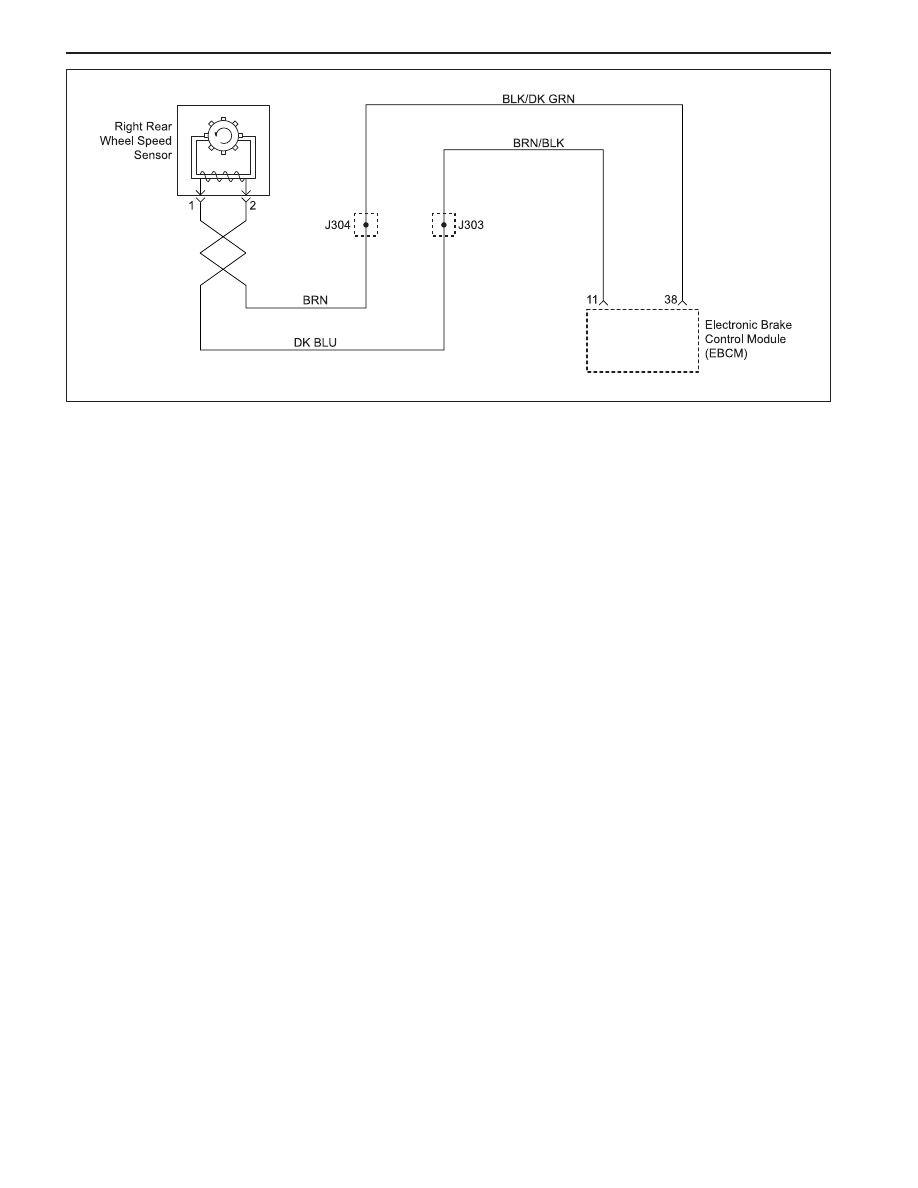
DIAGNOSTIC TROUBLE CODE (DTC) 10
RIGHT REAR WHEEL SPEED SENSOR CONTINUITY FAULT
KAA4F170
Circuit Description
The toothed wheel generates a voltage pulse as it
moves past the sensor. Each tooth-gap-tooth series
on the wheel generates the pulses. The electronic brake
control module (EBCM) uses the frequency of these
pulses to determine the wheel speed. The voltage gen-
erated depends on the air gap between the sensor and
the toothed wheel, and on the wheel speed.
Diagnosis
This procedure checks for a malfunctioning wheel speed
sensor, a short to ground or to voltage in the wiring, or
a contact problem in a connector.
Cause(s)
•
The wheel speed sensor is defective or discon-
nected.
•
There is a problem in the wiring.
•
There is a problem with a connector.
Fail Action
ABS action is disabled, and the ABS warning lamp is
ON.
Test Description
The number(s) below refer to step(s) on the diagnostic
table.
1. This step begins an examination for a defective
wheel speed sensor.
4. This step tests the wiring for a short to voltage.
6. This step tests the wiring for a short to ground.
8. This step tests for an open or a high resistance in
the wiring.
Diagnostic Aids
Be sure that the speed sensor wiring is properly routed
and retained. This will help to prevent false signals due
to the pickup of electrical noise.
It is very important to perform a thorough inspection of
the wiring and the connectors. Failure to inspect the
wiring and the connectors carefully and completely may
result in misdiagnosis, causing part replacement with
the reappearance of the malfunction.

ABS AND TCS 4F-53
SSANGYONG MY2002
Step
1
2
3
4
5
6
7
8
9
10
DTC 10 - Right Rear Wheel Speed Sensor Continuity Fault
Action
Go to Step 3
Go to Step 4
System OK
Go to Step 5
System OK
Go to Step 7
System OK
Go to Step 9
System OK
System OK
Go to Step 2
Go to Step 3
-
Go to Step 6
-
Go to Step 8
-
Go to Step 10
-
-
-
1280 - 1920
Ω
-
>1v
-
∞
-
>5
Ω
-
-
Examine the wheel speed sensor.
Are there any signs of physical damage?
1. Turn the ignition to LOCK.
2. Disconnect the left rear wheel speed sensor
connector.
3. Use a digital voltmeter (DVM) to measure resis-
tance between the sensor terminals.
Is the resistance within the specified value at ap-
proximately 25-C (77-F)?
Replace the wheel speed sensor.
Is the repair complete?
1. Disconnect the harness from the EBCM.
2. Connect a DVM between ground and one terminal
of the wheel speed connector.
3. Turn the ignition to ON.
4. Repeat the above test for the other terminal of the
wheel speed connector.
Is the voltage for either of these terminals within the
specified value?
Repair the short to voltage in the affected circuit.
Is the repair complete?
1. Turn the ignition to LOCK.
2. Measure the resistance to ground from terminal 38
at the harness EBCM connector.
3. Measure the resistance to ground from terminal 11
at the harness EBCM connector.
Is the resistance at either circuit less than the speci-
fied value?
Repair the short to ground in the affected circuit.
Is the repair complete?
1. Measure the resistance between terminal 38 at the
harness EBCM connector and the harness wheel
speed sensor connector.
2. Measure the resistance between terminal 11 at the
harness EBCM connector and the harness wheel
speed sensor connector.
Is the resistance on either circuit within the specified
value?
Repair the open or high resistance in the affected
circuit as required. Be sure to check junction J303
and J304.
Is the repair complete?
Replace the ABS unit.
Is the repair complete?
Value(s)
Yes
No
SSANGYONG MY2002
4F-54 ABS AND TCS
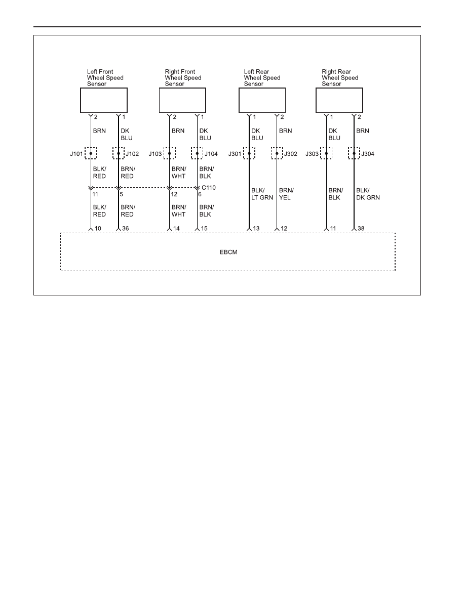
DIAGNOSTIC TROUBLE CODE (DTC) 11
WHEEL SPEED SENSOR FREQUENCY ERROR
KAA4F180
Circuit Description
The toothed wheel generates a voltage pulse as it
moves past the wheel speed sensor. Each tooth-gap-
tooth series on the wheel generates the pulses. The
electronic brake control module (EBCM) uses the fre-
quency of these pulses to determine wheel speed. The
voltage generated depends on the air gap between the
wheel speed sensor and the toothed wheel, and on the
wheel speed.
Diagnosis
This DTC will set when the EBCM cannot identify which
wheel speed sensor is causing the malfunction. It is
nec-essary to check all wheel speed sensors and
associated wiring to determine the cause of the DTC.
Cause(s)
•
Incorrect number of teeth on the toothed wheel.
•
Damaged or broken teeth on the toothed wheel.
•
Discontinuity or short in speed wheel speed sensor
wiring.
Fail Action
Antilock brake system (ABS) action is disabled and
the ABS warning lamp is ON.
Test Description
The number(s) below refer to Step(s) on the diagnostic
table.
1. This step begins the examination of the front wheel
speed sensor sensors.
3. This step checks for a problem with one of the
front toothed rings.
5. This step checks the front wheel speed sensors.
7. This step checks for shorts in a front wheel speed
sensor harness.
9. This step checks for opens in a front wheel speed
sensor harness.
11. This step begins a check of the rear wheel speed
sensors.
13. This step checks for a problem with one of the
rear toothed rings.
15. This step checks the rear wheel speed sensors.
17. This step checks for shorts in a rear wheel speed
sensor harness.
19. This step checks for opens in a rear wheel speed
sensor harness.
Нет комментариевНе стесняйтесь поделиться с нами вашим ценным мнением.
Текст