SsangYong Korando II (1996-2006 year). Manual — part 260

ABS AND TCS 4F-55
SSANGYONG MY2002
Diagnostic Aids
DTC 11 may be set by running the scan tool auto test
if the throttle angle readings are not updating while in
the data list mode. If this is the case, clear the DTCs,
disconnect the scan tool, and road test the vehicle to
at least 25 km/h (15 mph) to see if the DTC resets.
Check the toothed wheels for any large grooves,
gouges, marks, etc. that might influence the tooth’s
signal at the wheel speed sensor. Also, check for a
buildup of foreign material in the gaps between the teeth
in the toothed wheel, as this material may cause this
malfunction.
A badly worn hub/bearing assembly may cause this
malfunction. The wheel speed sensor-to-toothed wheel
air gap may change excessively due to bearing play.
If an improper rear hub assembly or front outer constant
velocity joint is installed, one with a toothed wheel con-
taining the incorrect number of teeth, this DTC can set.
Be sure that all the toothed wheels have 52 teeth.
Step
1
2
3
5
6
7
8
9
DTC 11 - Wheel Speed Sensor Frequency Error
Action
Go to Step 2
System OK
Go to Step 4
System OK
Go to Step 7
System OK
Go to Step 9
System OK
Go to Step 3
-
Go to Step 5
-
Go to Step 6
-
Go to Step 9
-
-
-
-
-
1280 - 1920
Ω
-
-
-
Visually inspect the wiring for the front wheel speed
sensors.
Is there any damage?
Repair or replace components, as required.
Is the repair complete?
Check that the correct outer constant velocity (CV)
joints are installed on the vehicle. They should have
speed rings with 52 teeth.
Is one of these incorrect?
Replace the incorrect outer CV joint with the proper
unit.
Is the repair complete?
1. Disconnect the wheel speed sensor harnesses
from the wheel speed sensor connectors.
2. Measure the wheel speed sensor resistance at the
wheel speed sensor connector terminals.
Does the resistance fall within the specified values for
both wheel speed sensors?
Replace the faulty wheel speed sensor.
Is the repair complete?
1. Disconnect the ABS control module connector.
2. Check each wheel speed sensor harness for a
short circuit between its wires with a digital ohmme-
ter attached to the two terminals at the harness
side of the wheel speed sensor connector.
3. Also check each wheel speed sensor harness wire
for a short to ground from the connector terminals.
Is there any short circuit in either wheel speed sensor
harness?
Repair the short circuit in the wiring or from a wiring
harness to ground.
Is the repair complete?
Value(s)
Yes
No

SSANGYONG MY2002
4F-56 ABS AND TCS
Step
9
10
11
12
13
14
15
16
DTC 11 - Wheel Speed Sensor Frequency Error (Cont’d)
Action
Go to Step 11
System OK
Go to Step 12
System OK
Go to Step 14
System OK
Go to Step 17
System OK
Go to Step 10
-
Go to Step 13
-
Go to Step 15
-
Go to Step 16
-
-
-
-
-
-
-
1280 - 1920
Ω
-
Check the continuity of the wiring in both front wheel
speed sensor circuits between the EBCM connector
and the wheel speed sensor connector on each side
of the vehicle.
•
The left side uses terminals 10 and 36 at the
EBCM connector.
•
The right side uses terminals 14 and 15 at the
EBCM connector.
Is continuity good for both harnesses?
Repair the discontinuity found in the front wheel
speed sensor harness or connectior C113.
Is the repair complete?
1. Visually inspect the wiring for the rear wheel
speed sensors.
2. Check that the wheel speed sensors are properly
mounted and that the retaining bolts are properly
tightened.
Is there any damage?
Repair or replace the components, as required.
Is the repair complete?
Remove each wheel speed sensor from the rear axle
and inspect the toothed ring through the wheel speed
sensor mounting holes.
•
Make sure that the toothed ring has 52 teeth.
•
Check for any damaged or missing teeth.
•
Check that the ring is properly positioned under
the wheel speed sensor.
Is there any damage or other fault with either speed
ring?
Replace the rear wheel hub with the proper unit.
Is the repair complete?
1. Disconnect the rear wheel speed sensor har-
nesses from the wheel speed sensor connectors.
2. Measure the wheel speed sensor resistance at the
wheel speed sensor connector terminals.
Does the resistance fall within the specified values for
both wheel speed sensors?
Replace the faulty wheel speed sensor.
Is the repair complete?
Value(s)
Yes
No

ABS AND TCS 4F-57
SSANGYONG MY2002
Step
17
18
19
20
21
DTC 11 - Wheel Speed Sensor Frequency Error (Cont’d)
Action
Go to Step 18
System OK
Go to Step 21
System OK
System OK
Go to Step 19
-
Go to Step 20
-
-
-
-
-
-
-
1. The ABS control module connector should still be
disconnected. Disconnect it now if it is not.
2. Check each wheel speed sensor harness for a short
circuit between its wires with a digital ohmmeter
attached to the two terminals at the harness side of
the wheel speed sensor connector.
3. Also, check each wheel speed sensor harness wire
for a short to ground from the connector terminals.
Is there any short circuit in either wheel speed sensor
harness?
Repair the short circuit in the wiring or from a wire to
ground.
Is the repair complete?
Check the continuity of the wiring in both rear wheel
speed sensor circuits between the EBCM connector
and the wheel speed sensor connector on each side
of the vehicle.
•
The left side uses terminals 12 and 13 at the
EBCM connector.
•
The right side uses terminals 11 and 38 at the
EBCM connector.
Is continuity good for both harnesses?
Repair the discontinuity found in the rear wheel speed
sensor harness.
Is the repair complete?
Replace the ABS unit.
Is the repair complete?
Value(s)
Yes
No
SSANGYONG MY2002
4F-58 ABS AND TCS
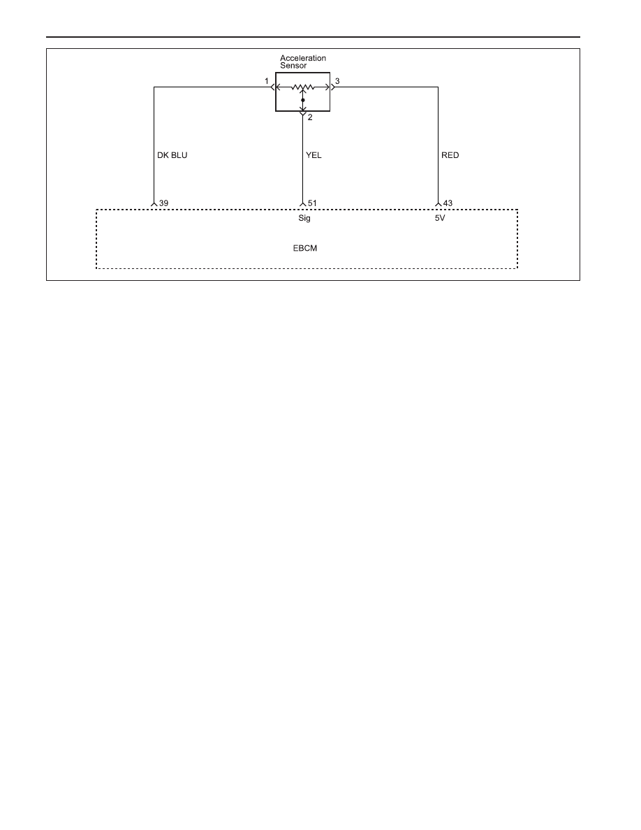
DIAGNOSTIC TROUBLE CODE (DTC) 42
ACCELERATION SENSOR FAULT
KAA4F190
Circuit Description
The acceleration sensor provides a voltage signal that
changes in relation to the acceleration of vehicle. The
signal voltage will vary from about 1.95 to 3.45 volt.
The electronic brake control module (EBCM) monitor a
signal voltage of deceleration in the vehicle.
Diagnosis
This procedure checks for a malfunctioning acceleration
sensor, a short to ground or to voltage in the wiring, or
a contact problem in a connector.
Cause
•
The vertical acceleration sensor is defective or dis
connected
•
There is a problem in the wiring
•
There is a problem with a connector
•
Wrong installed vertical acceleration sensor
Fail Action
ABS action is disabled, and the ABS warning lamp is
ON.
Test Description
The number(s) below refer to step(s) on the diagnostic
table.
2. This step checks for the voltage reference from
the EBCM.
5. This step checks for the voltage signal from the
acceleration sensor.
Diagnostic Aids
Be sure that the acceleration sensor wiring is properly
routed and retained.
It is very important to perform a thorough inspection of
the wiring and the connectors carefully and completely
may result in misdiagnosis, causing part replacement
with the reappearance of the malfunction.
You can use the scan tool to monitor acceleration sensor
during a road test. Watch the acceleration sensor being
displayed on the scan tool to see if any of the reading
is unusual.
Нет комментариевНе стесняйтесь поделиться с нами вашим ценным мнением.
Текст