SsangYong Korando II (1996-2006 year). Manual — part 403
SSANGYONG MY2002
8B-26 SUPPLEMENTAL RESTRAINTS SYSTEM
Circuit Description
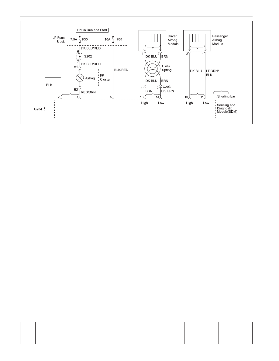
When the ignition switch is turned to ON, the sensing
and diagnostic module (SDM) will perform tests to
diagnose critical malfunctions within SDM itself. Upon
passing these tests ignition and deployment loop
voltages are measured to ensure that they are within
their respective normal voltage ranges. The SDM
monitors the voltages at the driver low (terminal 14),
p a s s e n g e r l o w ( t e r m i n a l 1 1 ) , d r i v e r s e a t b e l t
pretensioner low (terminal 7) and passenger seat belt
pretensioner low (terminal 4) to detect short to ground
in the deployment loops.
DTC 05 Will Set When
DTC 05 will set when the voltage at driver airbag low
falls below a specified value, and ignition voltage is
within the normal operating voltage range.
DIAGNOSTIC TROUBLE CODE (DTC) 05
DRIVER DEPLOYMENT LOOP SHORTED TO GROUND
This test is run during start-up test and every 250
milliseconds during continuous monitoring.
Action Taken
The SDM will turn on the airbag indicator (blink mode
3) and set DTC 05. The SDM will shutdown the driver
airbag module deployment loop.
DTC 05 Will Clear When
The scan tool CLEAR CODES command is received.
Diagnostic Aids
Carefully inspect the wires in driver airbag deployment
loop for cutting or chafing.
KAA8B100
DTC 05 - Driver Deployment Loop Shorted to Ground
Caution: The sensing and diagnosis module (SDM)
can maintain sufficient voltage to deploy the airbags
and pretensioners for 0.15 seconds after the ignition
is OFF and the fuse has been removed. If the airbags
or pretensioners are not disconnected, do not begin
s e r v i c e u n t i l o n e m i n u t e h a s p a s s e d a f t e r
disconnecting power to the SDM. Otherwise, injury
could result.
Caution: During service procedure, be very careful
when handling the SDM. Never strike or jar the SDM.
Never power the supplemental restraints system
(SRS) when the SDM is not rigidly attached to the
vehicle. Also SDM mounting nuts must be carefully
tightened to ensure proper operation of the SRS.
The SDM could be activated if it is powered when it
is not rigidly attached to the vehicle, resulting in
unexpected deployment and possible injury.
Perform the SRS Diagnostic System Check.
Is the SRS Diagnostic System Check complete?
Step
Action
Value(s)
Yes
No
1
-
Go to Step 2
-

SUPPLEMENTAL RESTRAINTS SYSTEM 8B-27
SSANGYONG MY2002
1. Disable the Supplemental Restraint System (SRS).
Refer to “Disabling the Supplemental Restraint
System (SRS)” in this section.
2. Virtually inspect the driver airbag circuit and
connectors, especially at the SDM.
Is there any evidence of rubbing, damage or chafing?
1. Repair the damaged wires or connectors.
2. Connect all the SRS components.
Is the repair complete?
1. Disconnect the SDM connector.
2. Disconnect driver airbag.
3. Turn the ignition ON.
4. Measure the resistance between terminal 1 (or 2) of
the driver airbag connector and ground.
Is the resistance within the specified value?
1. Disconnect C203.
2. Measure the resistance between terminal 1 (or 2) of
the driver airbag connector and ground.
Is the resistance within the specified value?
1. Repair short to ground in clock spring or replace
the clock spring as needed.
2. Connect all SRS components.
Is the repair complete?
1. Repair short to ground between SDM and C203.
2. Connect all SRS components.
Is the repair complete?
1. Connect dummy resistance (2.15 ± 0.35
Ω
) to
driver airbag connector instead of driver airbag.
2. Enable the SRS.
3. Connect the scan tool to the data link connector
(DLC).
4. Clear DTC and request DTC.
Is the DTC 05 still present?
Replace driver airbag.
Is the repair complete?
1. Replace SDM.
2. Connect all SRS components.
Is the repair complete?
Step
Action
Value(s)
Yes
No
2
4
5
6
-
Go to Step 3
Go to Step 4
3
-
Go to “SRS
Diagnostic
System Check”
-
∞
Go to Step 8
Go to Step 5
-
Go to “SRS
Diagnostic
System Check”
-
-
Go to “SRS
Diagnostic
System Check”
-
-
Go to “SRS
Diagnostic
System Check”
-
-
Go to Step 10
Go to Step 9
7
8
9
10
∞
Go to Step 7
Go to Step 6
-
Go to “SRS
Diagnostic
System Check”
-

SSANGYONG MY2002
8B-28 SUPPLEMENTAL RESTRAINTS SYSTEM
Circuit Description
When the ignition switch is turned to ON, the sensing
and diagnostic module (SDM) will perform tests to
diagnose critical malfunctions within SDM itself. Upon
passing these tests ignition and deployment loop
voltages are measured to ensure that they are within
their respective normal voltage ranges. The SDM
monitors the voltages at the driver low (terminal 14),
p a s s e n g e r l o w ( t e r m i n a l 1 1 ) , d r i v e r s e a t b e l t
pretensioner low (terminal 7) and passenger seat belt
pretensioner low (terminal 4) to detect short to ground
in the deployment loops.
DTC 06 Will Set When
DTC 06 will set when the voltage at passenger airbag
low falls below a specified value, and ignition voltage
is within the normal operating voltage range.
DIAGNOSTIC TROUBLE CODE (DTC) 06
PASSENGER DEPLOYMENT LOOP SHORTED TO GROUND
This test is run during start-up test and every 250
milliseconds during continuous monitoring.
Action Taken
The SDM will turn on the airbag indicator (blink mode
3) and set DTC 06. The SDM will shutdown the
passenger airbag deployment loop.
DTC 06 Will Clear When
The scan tool CLEAR CODES command is received.
Diagnostic Aids
Carefully inspect the wires in passenger airbag
deployment loop for cutting or chafing.
KAA8B100
DTC 06 - Passenger Deployment Loop Shorted to Ground
Caution: The sensing and diagnosis module (SDM)
can maintain sufficient voltage to deploy the airbags
and pretensioners for 0.15 seconds after the ignition
is OFF and the fuse has been removed. If the airbags
or pretensioners are not disconnected, do not begin
s e r v i c e u n t i l o n e m i n u t e h a s p a s s e d a f t e r
disconnecting power to the SDM. Otherwise, injury
could result.
Caution: During service procedure, be very careful
when handling the SDM. Never strike or jar the SDM.
Never power the supplemental restraints system
(SRS) when the SDM is not rigidly attached to the
vehicle. Also SDM mounting nuts must be carefully
tightened to ensure proper operation of the SRS.
The SDM could be activated if it is powered when it
is not rigidly attached to the vehicle, resulting in
unexpected deployment and possible injury.
Perform the SRS Diagnostic System Check.
Is the SRS Diagnostic System Check complete?
Step
Action
Value(s)
Yes
No
1
-
Go to Step 2
-

SUPPLEMENTAL RESTRAINTS SYSTEM 8B-29
SSANGYONG MY2002
1. Disable the Supplemental Restraint System (SRS).
Refer to “Disabling the Supplemental Restraint
System (SRS)” in this section.
2. Virtually inspect the passenger airbag circuit and
connectors, especially at the SDM.
Is there any evidence of rubbing, damage or chafing?
1. Repair the damaged wires or connectors.
2. Connect all the SRS components.
Is the repair complete?
1. Disconnect the SDM connector.
2. Disconnect passenger airbag.
3. Turn the ignition ON.
4. Measure the resistance between terminal 1 (or 2) of
the passenger airbag connector and ground.
Is the resistance within the specified value?
1. Repair short to ground in passenger airbag
deployment loop.
2. Connect all SRS components.
Is the repair complete?
1. Connect dummy resistance (2.15 ± 0.35
Ω
) to
passenger airbag connector instead of passenger
airbag.
2. Enable the SRS.
3. Connect the scan tool to the data link connector
(DLC).
4. Clear DTC and request DTC.
Is the DTC 06 still present?
Replace passenger airbag.
Is the repair complete?
1. Replace SDM.
2. Connect all SRS components.
Is the repair complete?
Step
Action
Value(s)
Yes
No
2
4
5
6
-
Go to Step 3
Go to Step 4
3
-
Go to “SRS
Diagnostic
System Check”
-
∞
Go to Step 6
Go to Step 5
-
Go to “SRS
Diagnostic
System Check”
-
-
Go to “SRS
Diagnostic
System Check”
-
-
Go to “SRS
Diagnostic
System Check”
-
-
Go to Step 8
Go to Step 7
7
8
Нет комментариевНе стесняйтесь поделиться с нами вашим ценным мнением.
Текст