SsangYong Korando II (1996-2006 year). Manual — part 378

HEATING AND VENTILATION SYSTEM 7A-9
SSANGYONG MY2002
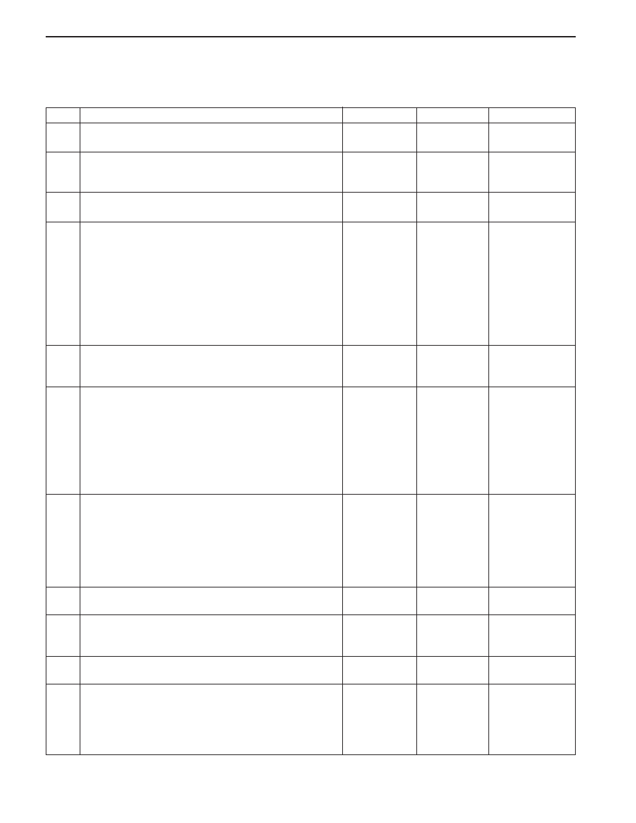
Blower Electrical (Cont’d)
Step
11
12
13
14
15
16
17
Action
Using ohmmeter, measure the resistance between
terminal 87 of blower motor relay.
Is the resistance within specified value?
Replace the blower motor relay.
Is the repair complete?
1. Disconnect blower motor switch connector.
2. Turn the ignition switch ON.
3. Jump terminal 5 and terminal 1 of the blower
motor switch connector with jump wire.
Does the blower motor run?
Repair open circuit between terminal 87 of blower
motor relay to ground G203.
Is the repair complete?
Replace the blower motor switch.
Is the repair complete?
1. Disconnect the blower motor switch connector.
2. Turn the ignition switch ON.
3. Using test light, check the power feed between
terminal 2, 3, 4, and 5 of the blower motor switch
connector and ground.
Does the light come on?
Repair open circuit or replace the blower resister.
Is the repair complete?
Yes
Go to Step 12
System OK
Go to Step 15
System OK
System OK
Go to Step 15
System OK
No
Go to Step 13
-
Go to Step 7
-
-
Go to Step 17
-
Value(s)
≈
0
Ω
SSANGYONG MY2002
7A-10 HEATING AND VENTILATION SYSTEM
MODE CONTROLS DO NOT WORK
Refer to “Non A/C Diagrams” for electrical schematic diagram of the circuits described in this procedure.
Mode Controls Do Not Work
Step
1
2
3
4
5
6
7
8
9
10
11
Action
Verify the customer’s complaint.
Are the customer’s concerns verified?
Measure the voltage between terminal 8 of heating
and ventilation control (HVC) controller and ground.
Is the voltage within the specified value?
Check fuse F19 in the I/P fuse block.
Is the fuse blown?
1. Turn the ignition ON.
2. Use a short detector to locate the following
possible short:
•
From the fuse F24 to terminal 8 of C204.
•
From the terminal 8 of the C212 to terminal 8 of
HVC controller.
3. Repair any short.
4. Replace any blown fuse.
Is the repair complete?
Repair open circuits from fuse F19 to terminal 8 of the
HVC controller.
Is the repair complete?
1. Turn the ignition switch to OFF.
2. Disconnect the mode actuator connector.
3. Using Motor Control Table, measure the resis-
tance between the specified terminals of the
specified motor connector.
4. Change the mode settings and observe the
resistance change.
Are the resistance equal to specified value?
1. Disconnect the HVC controller.
2. Using Motor Control Table, measure the resis-
tance between the specified terminals of the
specified HVC controller.
3. Change the mode settings and observe the
resistance change.
Are the resistance equal to specified value?
Replace the HVC controller.
Is the repair complete?
Repair open or short circuits between HVC controller
and mode moor actuator.
Is the repair complete?
Replace mode control motor.
Is the repair complete?
1. Examine the affected door in the unit for proper
attachment to the actuator.
2. Check the actuator connection to the door.
3. Check that the connector is properly connected.
Is everything connected properly?
Yes
Go to Step 2
Go to Step 6
Go to Step 4
System OK
System OK
Go to Step 10
Go to Step 9
System OK
System OK
System OK
Go to Step 13
No
System OK
Go to Step 3
Go to Step 5
-
-
Go to Step 7
Go to Step 8
-
-
Go to Step 11
Go to Step 12
Value(s)
-
11 - 14 v
See the
“Motor Control
Table”
See the
“Motor Control
Table”
HEATING AND VENTILATION SYSTEM 7A-11
SSANGYONG MY2002
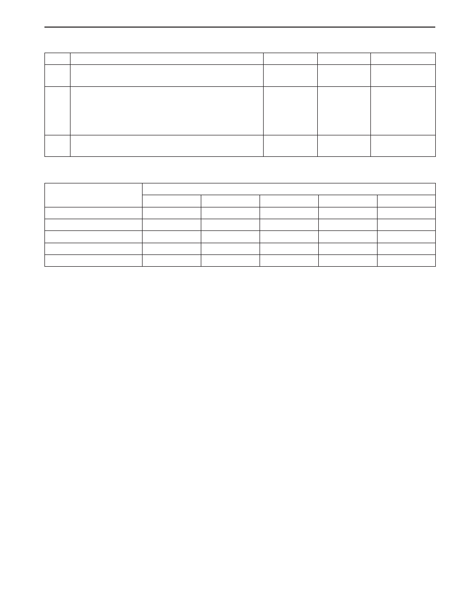
Defrost (Terminal 5/9)
Defrost/Foot (Terminal 5/9)
Foot (Terminal 5/9)
Bi-Level (Terminal 5/9)
Vent (Terminal 5/9)
Mode Controls Do Not Work (Cont’d)
Step
12
13
14
Action
Repair as necessary.
Is the repair complete?
1. Disconnect the actuator at the door.
2. Check the range of the door travel and the effort
required moving it.
Does the door move freely through its entire range of
travel so that it can close at both ends of the range?
Adjust the door travel and repair as necessary.
Is the repair complete?
Yes
System OK
Go to Step 5
System OK
No
-
Go to Step 12
-
Value(s)
6/7
3.9 - 4.1
Ω
3.9 - 4.1
Ω
≈
0
Ω
≈
0
Ω
≈
0
Ω
14/8
3.9 - 4.1
Ω
≈
0
Ω
≈
0
Ω
≈
0
Ω
≈
0
Ω
Connector Terminal (Controller / Motor)
Mode Setting
Motor Control Table
15/6
3.9 - 4.1
Ω
3.9 - 4.1
Ω
3.9 - 4.1
Ω
≈
0
Ω
≈
0
Ω
7/5
3.9 - 4.1
Ω
3.9 - 4.1
Ω
3.9 - 4.1
Ω
3.9 - 4.1
Ω
≈
0
Ω
16/4
3.9 - 4.1
Ω
3.9 - 4.1
Ω
3.9 - 4.1
Ω
3.9 - 4.1
Ω
3.9 - 4.1
Ω
SSANGYONG MY2002
7A-12 HEATING AND VENTILATION SYSTEM
AIR SOURCE SELECTION NOT CONTROLLED
Refer to “Non A/C Diagrams” for electrical schematic diagram of the circuits described in this procedure.
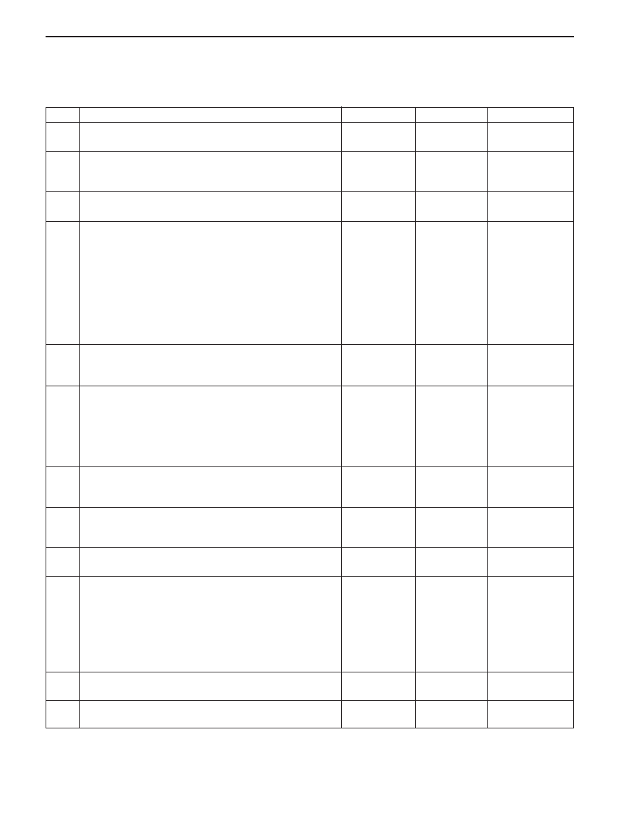
Air Source Selection Not Controlled
Step
1
2
3
4
5
6
7
8
9
10
11
12
Action
Verify the customer’s complaint.
Are the customer’s concerns verified?
Measure the voltage between terminal 8 of heating
and ventilation control (HVC) controller and ground.
Is the voltage within the specified value?
Check fuse F19 in the I/P fuse block.
Is the fuse blown?
1. Turn the ignition ON.
2. Use a short detector to locate the following
possible short:
•
From the fuse F19 to terminal 8 of C212.
•
From the terminal 8 of the C212 to terminal 8 of
HVC controller.
3. Repair any short.
4. Replace any blown fuse.
Is the repair complete?
Repair open circuits from fuse F19 to terminal 8 of the
HVC controller.
Is the repair complete?
1. Turn the ignition switch to OFF.
2. Disconnect the intake air control actuator connec-
tor.
3. Measure the voltage at terminal 3 of the connec-
tor.
Is the voltage within the specified value?
Repair open circuit from terminal 8 of C212 to termi-
nal 3 of the intake air actuator.
Is the repair complete?
Measure the resistance between terminal 2 and 3 of
the actuator.
Is the resistance within the specified value?
Replace the intake air door actuator.
Is the repair complete?
1. Disconnect the HVC controller.
2. Measure the resistance between following point:
•
Terminal 9 of HVC controller and terminal 1 of
actuator.
•
Terminal 10 of HVC controller and terminal 2 of
actuator.
Is the resistance within the specified value?
Repair open or short circuit.
Is the repair complete?
Replace the HVC controller.
Is the repair complete?
Yes
Go to Step 2
Go to Step 6
Go to Step 4
System OK
System OK
Go to Step 8
System OK
Go to Step 10
System OK
Go to Step 12
System OK
System OK
No
System OK
Go to Step 3
Go to Step 5
-
-
Go to Step 7
-
Go to Step 9
-
Go to Step 11
-
-
Value(s)
-
11 - 14 v
11 - 14 v
≈
2 k
Ω
≈
0
Ω
Нет комментариевНе стесняйтесь поделиться с нами вашим ценным мнением.
Текст