SsangYong Korando II (1996-2006 year). Manual — part 376
SECTION 7A
HEATING AND VENTILATION SYSTEM
CAUTION: The cooling system is pressurized when hot. Injury can result from removing the coolant reservoir
cap before the engine is sufficiently cool.
TABLE OF CONTENTS
Description and Operation . . . . . . . . 7A-2
Heating and Ventilation System . . . . . . . 7A-2
Components Locator . . . . . . . . . . .. 7A-3
Heater System . . . . . . . . . . . . ... 7A-3
Diagnostic Information and Procedures . . .. 7A-4
Heater System . . . . . . . . . . . . ... 7A-4
Blower Electrical . . . . . . . . . . . . 7A-8
Mode Controls Do Not Work . . . . . . . . 7A-10
Air Source Selection Not Controlled . . . . .. 7A-12
Temperature Controls Do Not Work . . . . .. 7A-13
Too Much Heat . . . . . . . . . . . . . 7A-14
Blower Noise . . . . . . . . . . . . . 7A-16
Repair Instructions . . . . . . . . . . . 7A-18
On-Vehicle Service . . . . . . . . . . . .. 7A-18
Temperature Control Cable Adjustment . . . 7A-18
Controller Assembly and Temperature
Control Cable . . . . . . . . . . . . . 7A-18
Control Assembly Knob Lighting . . . . . .. 7A-19
Air Intake Door Actuator . . . . . . . . ... 7A-19
Mode Control Door Actuator . . . . . . . . 7A-20
Heater/Air Distributor Case Assembly . . . .. 7A-20
Blower Motor . . . . . . . . . . . . . 7A-21
Blower Resistor . . . . . . . . . . . . 7A-22
Blower Unit . . . . . . . . . . . . . ... 7A-22
Heater Inlet Hose . . . . . . . . . . . .. 7A-23
Heater Outlet Hose . . . . . . . . . . ... 7A-23
Heater Core . . . . . . . . . . . . . .. 7A-24
Rear Heater Duct . . . . . . . . . . . .. 7A-24
Air Filter . . . . . . . . . . . . . . . 7A-24
Specifications . . . . . . . . . . . . . 7A-25
Heater Temperature Specification . . . . . . 7A-25
Heater Unit . . . . . . . . . . . . . ... 7A-25
Fastener Tightening Specification . . . . . . 7A-25
Schematic and Routing Diagrams . . . . ... 7A-26
Non - A/C Wiring Diagram . . . . . . . . 7A-26
Airflow Through Vents . . . . . . . . . ... 7A-28
SSANGYONG MY2002
7A-2 HEATING AND VENTILATION SYSTEM
DESCRIPTION AND OPERATION
HEATING AND VENTILATION
SYSTEM
The base heater system is designed to provide heating,
ventilation, windshield defrosting, side wind defogging
and rear seat area.
The heater and fan assembly blower regulates the air-
flow from the air inlet for further processing and distribu-
tion.
The heater core transfers the heater from the engine
coolant to the inlet air.
The temperature door regulates the amount of the air
that passes through the heater core. The temperature
door also controls the temperature of the air by control-
ling mix of heated air with the ambient air.
The mode door regulates the flow and distribution of
the processed air to the heater ducts and to the defroster
ducts.
The console mounted heating and ventilation control
panel contains one rotary control knob, one sliding con-
trol lever and six push control knobs, which operate as
follows:
Sliding Temperature Control Lever
•
Actuates by cable.
•
Raise the temperature of the air entering the vehicle
by sliding to the right, or the red portion of the knob.
Five Mode Control Knob
•
Actuates by electricity.
•
R e g u l a t e s t h e a i r d i s t r i b u t i o n b e t w e e n t h e
windshield, the instrument panel, and the floor
vents.
Rotary Blower Control Knob
•
Turns on to operate the blower motor at four speeds.
•
Turns OFF to stop the blower.
•
Operates completely independently from both the
mode control knob and temperature control knob.
•
Changes the fan speed in any mode and at any
speed.
Intake Air Control Knob
•
Operates by electricity.
•
Switches between recirculating the passenger
compartment air and bringing outside air into the
passenger compartment.
•
Is normally in fresh air mode.
•
Illuminates the indicator lamp when in the recalculat
ing mode.
Heater Core
The heater core heats the air before enters the vehicle.
Engine coolant is circulated through the core to heat
the outside air passing over the fins of the core. The
core is functional at all times and may be used to
temper conditioned air in the A/C mode as well as in
the heat or the vent mode.
HEATING AND VENTILATION SYSTEM 7A-3
SSANGYONG MY2002
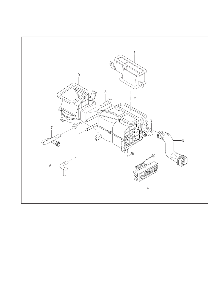
COMPONENTS LOCATOR
HEATER SYSTEM
1 Heater-to-Defrost Duct
2 Heater Unit
3 Mode Actuator Assembly
4 Heater Controller
5 Side Air Vent
6 Coolant Outlet Hose
7 Coolant Inlet Hose
8 Heater-to-Blower Duct
9 Blower Unit
KAA7A010

SSANGYONG MY2002
7A-4 HEATING AND VENTILATION SYSTEM
DIAGNOSTIC INFORMATION AND PROCEDURES
HEATER SYSTEM
Insufficient Heating or Defrosting
CAUTION: The cooling system is pressurized when hot. Injury can result from removing the coolant reservoir
cap before the engine is sufficiently cool.
Step
1
2
3
4
5
6
7
8
9
10
11
12
Action
Verify the customer’s complaint.
Are the customer’s concerns verified?
Check the coolant level.
Is the coolant level correct?
Add coolant as needed
Is the repair complete?
Check the serpentine accessory drive belt for tension
or damage.
Is the ’serpentine accessory drive belt OK?
Correct any problem with serpentine accessory drive
belt.
Is the repair complete?
Check the coolant hoses for leaks or kinks.
Are the coolant hoses OK?
Repair any problem with the coolant hoses.
Is the repair complete?
Check the coolant reservoir cap. Refer to Section 1D,
Engine Cooling.
Is the coolant reservoir cap OK?
Repair or replace the coolant reservoir cap as needed.
Is the repair complete?
1. Set the A/C switch OFF on the vehicles equipped
with air conditioning.
2. Set the temperature control lever to full hot.
3. Set the blower motor switch on 4.
4. Turn the ignition ON.
5. Check for the airflow from the vent outlet.
Is there a heavy airflow from the vent outlet?
Check for change in the airflow at various blower
speeds.
Does the blower speed increase as the switch is turned
from 1 to 4?
1. With the engine sufficiently cool, remove the
coolant reservoir cap.
2. Set the blower motor switch on 4.
3. Set the temperature control lever to full hot.
4. Start the engine and idle the engine.
5. Watch for the flow of the coolant.
Is the coolant flow visible?
Yes
Go to Step 2
Go to Step 4
System OK
Go to Step 5
System OK
Go to Step 8
System OK
Go to Step 10
System OK
Go to Step 11
Go to Step 12
Go to Step 16
No
System OK
Go to Step 3
Go to Step 4
Go to Step 6
Go to Step 6
Go to Step 7
Go to Step 8
Go to Step 9
Go to Step 10
Go to Step 25
Go to “Blower
Electrical”
Go to Step 13
Value(s)
-
Нет комментариевНе стесняйтесь поделиться с нами вашим ценным мнением.
Текст